
Velocity based control process for a machine digging cycle

a control process and automatic digging technology, applied in the field of automatic digging control process and system, can solve the problems of -based systems performing relatively well, operating efficiency in a work cycle may be less than optimal, and operator fatigue from operating various controls

Active Publication Date: 2008-04-24
CATERPILLAR INC
View PDF6 Cites 40 Cited by
  • Summary
  • Abstract
  • Description
  • Claims
  • Application Information

AI Technical Summary

Benefits of technology

[0007]In one aspect, the present disclosure provides a method of controlling a machine having an implement system that includes a linkage and a bucket coupled with the linkage. The method includes moving the implement system through a work cycle, including interacting with a material, and sensing values associated with a bucket velocity parameter during interacting with material. The method further includes controlling the bucket velocity parameter by controlling a sequence of bucket orientations whereby the implement system interacts with material. Controlling the bucket velocity parameter further includes outputting actuator control commands for at least one actuator of the implement system with an electronic controller of the machine responsive to the sensed values.
[0008]In another aspect, the present disclosure provides a machine including an implement system having a linkage with a boom and a stick, a bucket and a plurality of actuators. The machine further includes at least one sensor configured to sense values associated with a bucket velocity parameter, and an electronic controller. The electronic controller is coupled with the at least one sensor and with each of the actuators and is configured to control the bucket velocity parameter by controlling a sequence of bucket orientations whereby the implement system interacts with material responsive to signals from the at least one sensor.
[0009]In still another aspect, the present disclosure provides a control system for an excavating machine having an implement system that includes a linkage with a boom and stick, and a bucket. The control system includes at least one sensor configured to output signals indicative of a bucket velocity parameter. The control system further includes an electronic controller coupled with the at least one sensor. The electronic controller is configured to control the bucket velocity parameter by controlling a sequence of bucket orientations whereby the implement system interacts with material responsive to signals from the at least one sensor.

Problems solved by technology

For operations which are relatively lengthy, complex and / or repetitive, the operator may experience significant fatigue from operating the various controls repetitiously.
Moreover, operating efficiency in a work cycle may be less than optimal given the inherent limitations of human coordination, concentration and stamina.
Such force-based systems have performed relatively well in the past, however, they are not without limitations.
In other words, no practicable one-size-fits-all approach has been developed, with the result that conventional digging cycle control systems are often programmed via a plurality of different maps which correspond to a plurality of different material types, often following extensive field testing and tuning.

Method used


Image

  • Velocity based control process for a machine digging cycle
  • Velocity based control process for a machine digging cycle
  • Velocity based control process for a machine digging cycle

Examples


Embodiment Construction

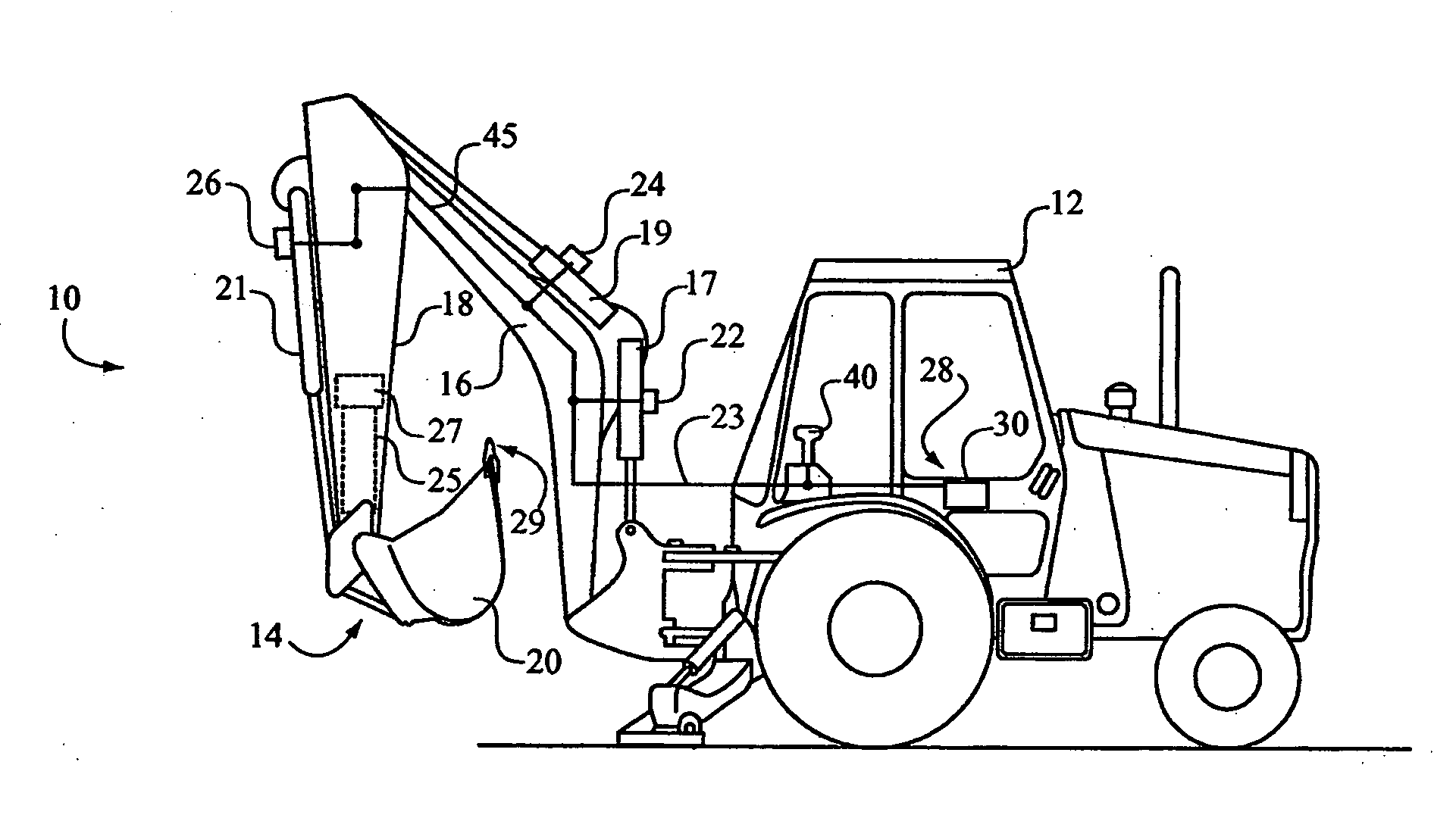
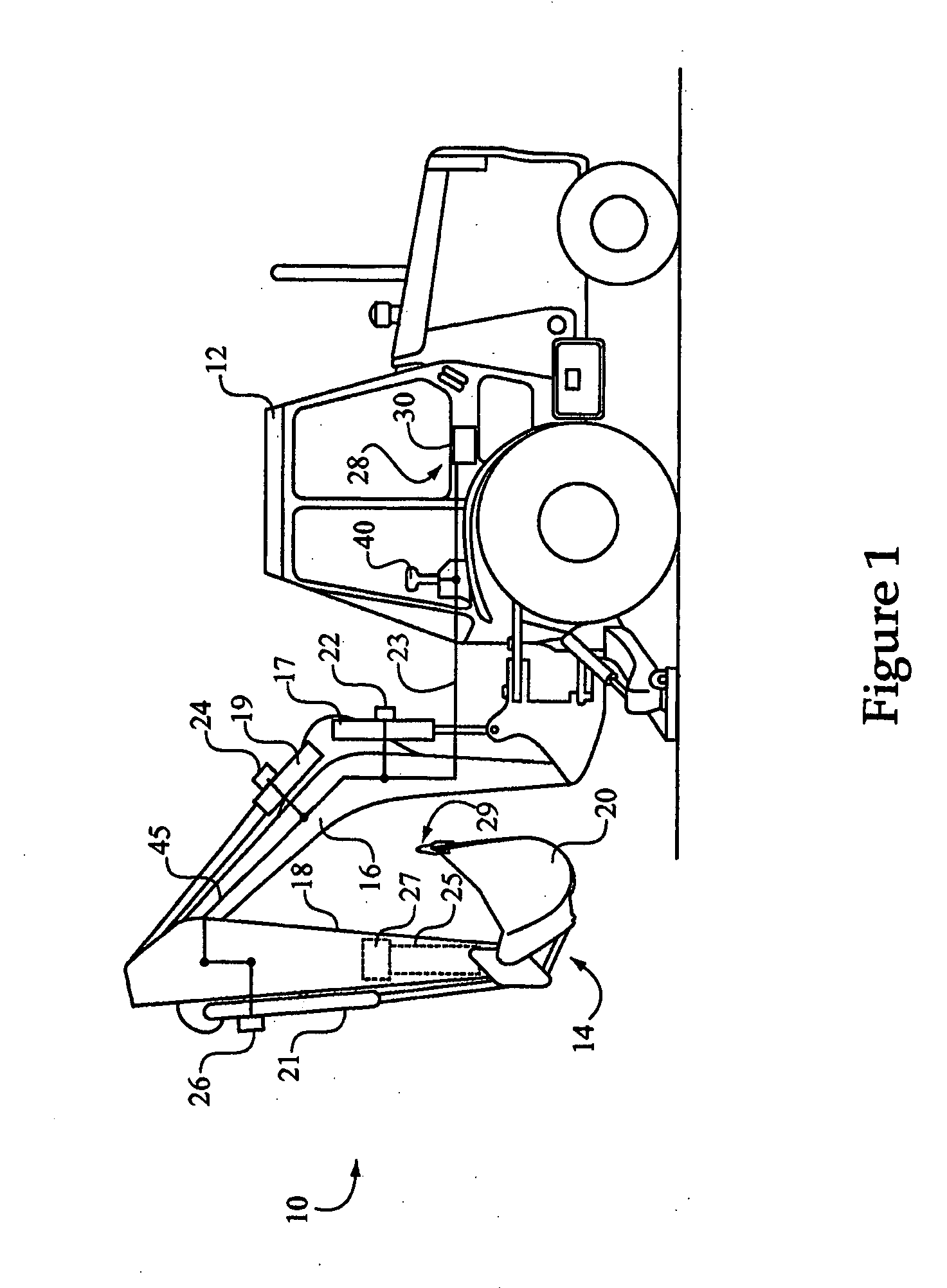
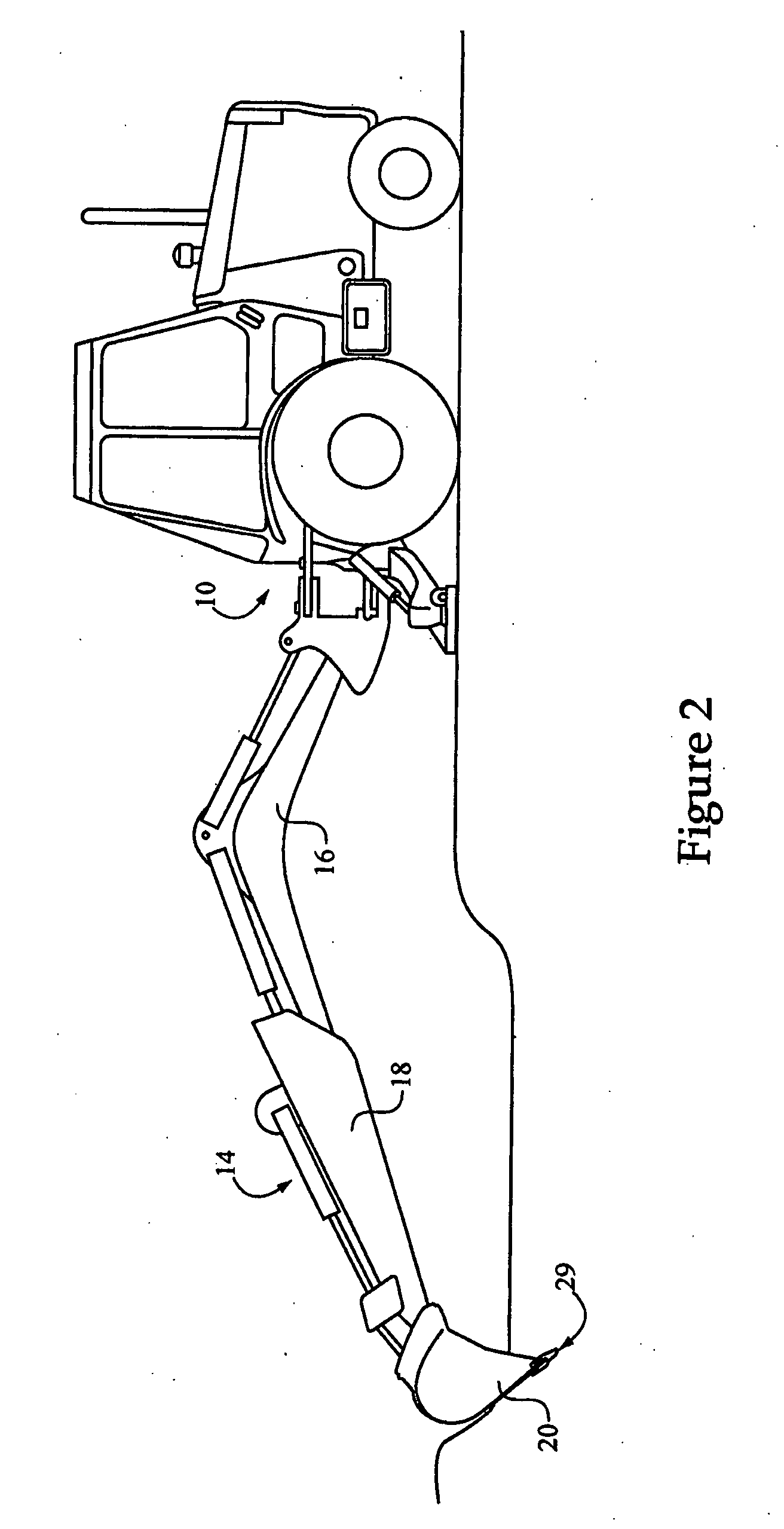
[0016]Referring to FIG. 1, there is shown a machine 10 having a control system 28, in accordance with one embodiment of the present disclosure. Machine 10 is illustrated approximately as it might appear in a start or tucked position, just prior to beginning performing a work cycle such as an automated digging cycle according to the present disclosure. Machine 10 is shown in the context of a backhoe-type excavator having a frame 12 with an implement system 14 coupled therewith, although the present disclosure is not thereby limited. Implement system 14 includes a boom 16, a stick 18 and a bucket 20 having a toothtip or bucket tip 29. It should be appreciated that other machine types such as tracked excavators, loaders, front shovels, etc., are contemplated as falling within the scope of the present disclosure. A plurality of actuators, which may be hydraulic actuators, are configured to move implement system 14 through a work cycle, comprising a boom actuator 17, a stick actuator 19 ...


PUM


Abstract

A method and machine with an automated digging cycle is provided. The method includes moving an implement system of the machine through a work cycle, including interacting with a material. The method further includes sensing values associated with a bucket velocity parameter, such as bucket tip velocity, during interacting with the material, and controlling the velocity parameter via commands which control a sequence of bucket orientations whereby an implement system of the machine interacts with the material, responsive to the sensed values. The machine includes an electronic controller configured via a control algorithm to execute the automated digging cycle. A velocity based control system for an excavating machine includes an electronic controller configured to receive velocity signals from at least one sensor, determine a bucket tip velocity, and output control commands to move a bucket of the excavating machine through a material via a sequence of bucket orientations that is based on the determined bucket tip velocity.

Description

[0001]This Application claims the Benefit of the Filing Date of U.S. Provisional Application Ser. No. 60 / 852,809, filed Oct. 19, 2006.TECHNICAL FIELD[0002]The present disclosure relates generally to control processes and systems for machines having an implement system, and relates more particularly to a velocity based control process and system for operating a machine implement system in an automated digging cycle.BACKGROUND[0003]A wide variety of construction machines are used to perform digging and digging-related tasks such as trenching, material spreading, grading, etc. An excavating machine is one such device, and a conventional design employs a multi-part linkage coupled with a bucket for capturing and moving material during a digging cycle. Each of the linkage components and the bucket will typically have one or more actuators coupled therewith. Each of the actuators, or actuator groups, may be coupled with separate control levers or other input devices. When it is desirable ...

Claims


Application Information

Patent Timeline
Patent Type & Authority Applications(United States)
IPC IPC(8): G06F19/00
CPCE02F3/434E02F9/2029E02F3/437
Inventor CLARK, MEGANMAGSTADT, CHADMETTLACH, GREGORYPRICE, ROBERT J.ALSHAER, BASSAM J.
Owner CATERPILLAR INC
Learn More