Eureka AIR delivers breakthrough ideas for toughest innovation challenges, trusted by R&D personnel around the world.

Compact rtd instrument panels and computer interfaces

Inactive Publication Date: 2008-04-17
APPLE INC
View PDF99 Cites 71 Cited by
  • Summary
  • Abstract
  • Description
  • Claims
  • Application Information

AI Technical Summary

Benefits of technology

[0026] The invention herein is particularly concerned with optical arrangements for the RTD and in particular prism based or mirror based optical systems which are optimized for the automotive center stack application in terms of small size (particularly in the depth direction), brightness and cost, as well as offering improved performance relative to problems encountered in the automotive environment, such as vibration, condensation (on optical elements) and ease of assembly and manufacture. The prism of the invention typically has one or more faces which are coated to reflect light inside the prism, although total internal reflection can be used where feasible and desirable.
[0048] It is a goal of the invention to provide a unique and easy to use interface accessory for cell phones, and to utilize the services of the cell phone where possible to lower the cost of the interface.

Problems solved by technology

In addition the ambient conditions are far more severe than home TV, exhibition or store display situation where the prior art lies.

Method used


Image

  • Compact rtd instrument panels and computer interfaces
  • Compact rtd instrument panels and computer interfaces
  • Compact rtd instrument panels and computer interfaces

Examples


embodiment 200

[0077]FIG. 2 Illustrates a double reflection prism embodiment 200 for a tall center stack application having the screen and control surface 210 mounted to the prism by mounts 211 and 212 and other mounting points not shown as desired. It also illustrates a variable shape mirrored prism surface to enhance resolution and brightness in the upper display region A compared to the lower region B.

[0078] While shown with the same shape as the output face 220 of the prism, control surface 210 can have a different curvature, since it may be desirable to make different screen and control surfaces work with same prism type, in order to achieve high volume production of the prism. This version is one of many potential embodiments that essentially provide a lengthened vertical beam path from the projector device (e.g. a Symbol laser scan projector or a Mitsubishi DLP Pocket projector).

[0079] As in FIG. 1, the output window of projector 215 is optically coupled to the prism top face 216, and the ...

embodiment 1000

[0130]FIG. 10a illustrates an embodiment 1000 similar to that of FIG. 9 but utilizing a laser scanning projector, and employing an off-axis Fresnel lens-like optical arrangement which may be specially designed to optimize light propagation to region of the users eyes similar to that shown in my previous applications.

[0131] As shown in the figure, a scanning laser projector 1010 such as a Microvision brand (Redmond Wash.) Pico projector, or Symbol LPD, which may be alternatively used instead of a DLP type as disclosed above and in co pending applications. The projector directs light over a wide projection angle in both of its angular axes to a mirror (which may be aspheric) 1015 and thence to an off-axis Fresnel lens 1020 placed just before the screen 1030. The Fresnel lens can be a specialized type having prismatic facets also designed to direct and converge light at different angles from the screen toward the user in a manner like that shown in FIG. 7 of my co pending application f...


PUM


Abstract

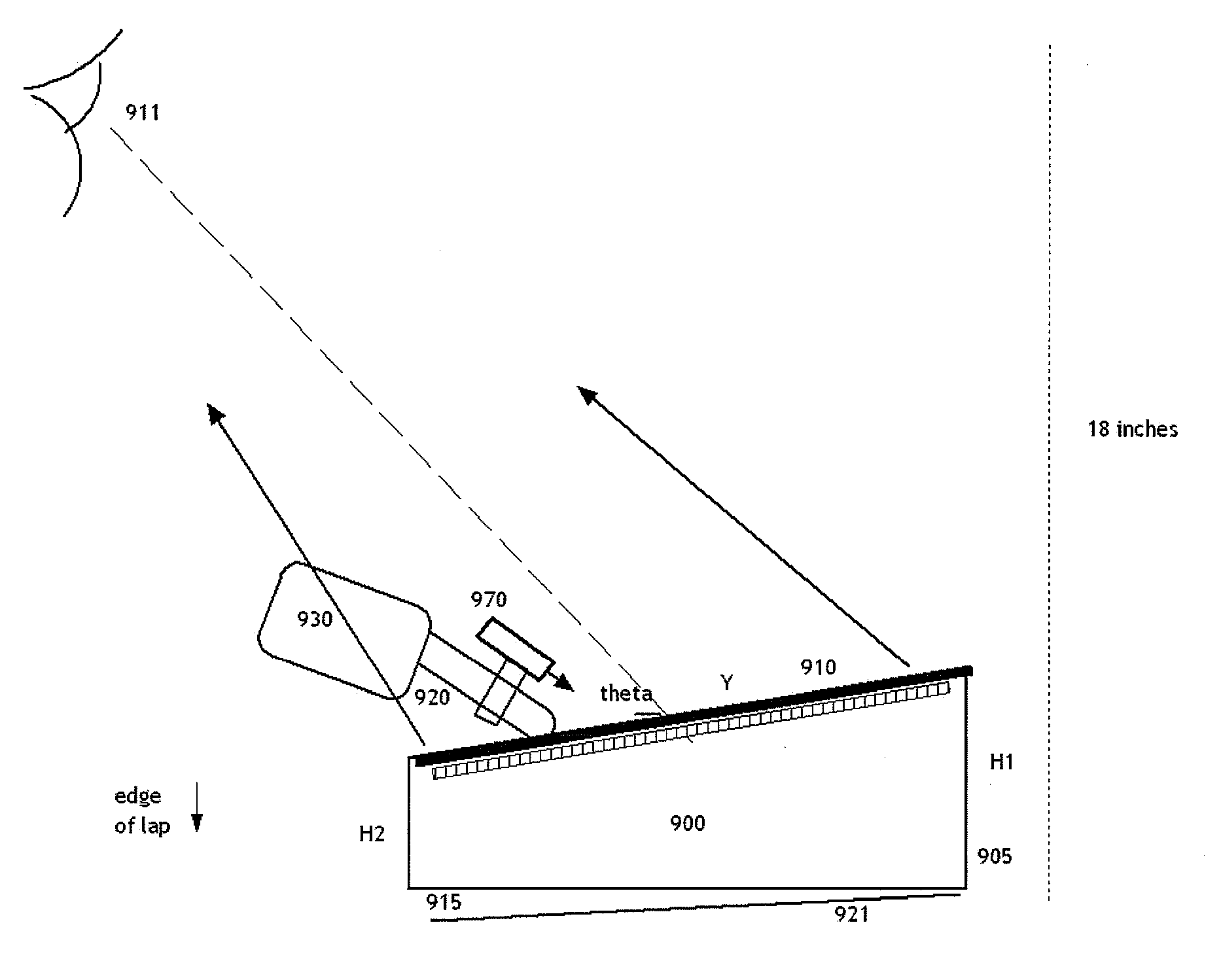
This concerns my RTD invention disclosed in co pending applications, particularly but not necessarily for use in the “center stack” region of vehicle instrument panels. Disclosed are novel prism devices to shrink the size of the unit, while increasing resistance to vibration and condensation and providing easier assembly into the vehicle. Also disclosed are methods to improve the efficiency of such projector based systems for delivering display light to the driver of the vehicle, as well as to reduce noise caused by backscatter from the screen and control surface, or sunlight coming through the windshield. RTD versions for home or office use are also disclosed, including a ““cushion computer”-like device meant primarily for use on one's lap and optionally having a reconfigurable keyboard. The device can also serve as a TV remote and perform other useful functions in the home, workplace, or car, and may serve as a useful interface accessory to expand the usability and enjoyment of mobile devices.

Description

CROSS REFERENCE TO RELATED APPLICATIONS [0001] This application claims benefit of U.S. Provisional Application No. 60 / 844,082 filed Sep. 13, 2006, (which is hereby incorporated by reference). [0002] This application is a continuation in part of U.S. Ser. No. 11 / 349,350 filed Feb. 8, 2006, entitled “Methods and Apparatus for Sensor based Control Displays”. [0003] This application is a continuation in part of Ser. No. 11 / 319,807 filed on Dec. 29, 2005, entitled “Reconfigurable Tactile Controls and Displays”. [0004] This application is a continuation in part of Ser. No. 11 / 184,076 filed on Jul. 18, 2005 entitled “Multi-functional Control and Entertainment Systems”. [0005] This application is also a continuation in part of Ser. No. 11 / 045,131 filed on Jan. 31, 2005, entitled “Reconfigurable tactile control displays for automobile instrument panels and other applications”. [0006] This application is also a continuation in part of PCT / US2004 / 09701 filed Mar. 31, 2004, entitled “Reconfigur...

Claims


Application Information

Patent Timeline
IPC IPC(8): G06F3/033H04N9/31
CPCH04N9/3129
Inventor PRYOR, TIMOTHY
Owner APPLE INC
Why Eureka
Eureka Blog
Learn More