
Artificial Blood Vessel and Method for Manufacturing Thereof

Inactive Publication Date: 2008-04-10
DAI NIPPON PRINTING CO LTD
View PDF4 Cites 5 Cited by
  • Summary
  • Abstract
  • Description
  • Claims
  • Application Information

AI Technical Summary

Benefits of technology

[0027]According to the present invention, it is possible that, for example, nutrients can be supplied to a cell in a tissue similar to a living tissue, the present invention exerts the effect that artificial blood vessels capable of being used for a variety of uses can be efficiently formed in a pattern in which artificial blood vessels are targeted.

Problems solved by technology

Moreover, disorders, in which an infarct in micro blood vessels within the living body occurs, and the supply of oxygen and nutrients or the transfer of metabolic decomposition products are not sufficiently performed exist.
To respond to such problems, conventionally, for example, artificial formation of the capillary blood vessels has been attempted by the techniques of the Non-Patent Documents 1 to 3, however, in either case, only the vessel-like tissues (capillaries) are formed in disorder so that it has been difficult to form capillary blood vessels capable of providing a necessary amount of the blood to a desired position for maintaining the function of the artificial tissues or infarct site treatment of micro blood vessels.
Moreover, as described in Non-Patent Document 4 or 5, a forming method of blood vessels by utilizing an artificial material has been studied, however, it is difficult to form narrow blood vessels and the artificial blood vessels which can be utilized for infarct site treatment of micro blood vessels and the construction of an artificial tissue could not be formed.
However, the technology for forming these blood vessels in a form suitable for the infarction site treatment of the micro blood vessels and the construction of the above-described artificial tissue has not yet been invented.[Non-Patent Documents 1] D. E. Ingber, et al., The Journal of Cell Biology (1989) p.

Method used


Image

  • Artificial Blood Vessel and Method for Manufacturing Thereof
  • Artificial Blood Vessel and Method for Manufacturing Thereof
  • Artificial Blood Vessel and Method for Manufacturing Thereof

Examples


first embodiment

(1) FIRST EMBODIMENT

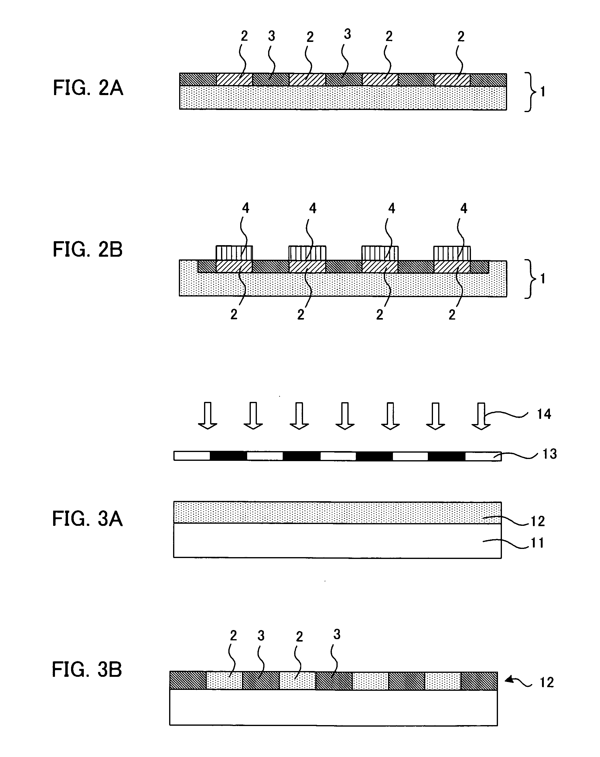
[0060]First, as a first embodiment, the cell culturing layer is a photocatalyst-containing cell adhesion layer comprising at least photocatalyst, the adhesive properties with cells and a blood vessel cell adhesive material which is decomposed or denatured by the action of a photocatalyst accompanying with the energy irradiation; and it is a case where for example, the cell adhesion-inhibiting portion is formed by decomposing or denaturing the blood vessel cell adhesive material by irradiating energy using such as a photomask having the light shielding portion in a pattern form of the blood vessel formation pattern on the photocatalyst-containing cell adhesion layer.

[0061]According to the present embodiment, since the photocatalyst-containing cell adhesion layer contains a photocatalyst and the blood vessel cell adhesive material, the area where the energy has been irradiated can be made the cell adhesion-inhibiting portion which is not adhered to the blood vessel...

second embodiment

(2) SECOND EMBODIMENT

[0104]Next, as a second embodiment, the cell culturing layer is a photocatalyst-containing cell adhesion-inhibiting layer containing at least a photocatalyst, and a blood vessel cell adhesion-inhibiting material having the cell adhesion-inhibiting properties for inhibiting the adhesion with the blood vessel cell and decomposed or denatured by the action of the photocatalyst accompanying with the energy irradiation; and it is a case where a cell adhesion portion is formed by decomposing or denaturing the blood vessel cell adhesion-inhibiting material by irradiating the energy on the photocatalyst-containing cell adhesion-inhibiting layer, for example, using a photomask having the opening portion in a pattern form of the blood vessel formation pattern.

[0105]In the present embodiment, since the photocatalyst-containing cell adhesion-inhibiting layer contains the photocatalyst and the blood vessel cell adhesion-inhibiting material, the blood vessel cell adhesion-inh...

third embodiment

(3) THIRD EMBODIMENT

[0138]Next, as a third embodiment; the cell culturing layer is a blood vessel cell adhesion layer having the adhesive properties with the blood vessel cell and containing a blood vessel cell adhesive material decomposed or denatured by the action of the photocatalyst accompanying with the energy irradiation, formed on the photocatalyst-containing layer containing at least a photocatalyst; and it is a case where a cell adhesion-inhibiting portion is formed on the blood vessel cell adhesion layer by decomposing or denaturing the blood vessel cell adhesive material by irradiating the energy using for example a photomask having the light shielding portion in a pattern form of the blood vessel formation pattern.

[0139]In the present embodiment, since the blood vessel cell adhesion layer is formed on the photocatalyst-containing layer by the energy irradiation, the blood vessel cell adhesive material in the blood vessel cell adhesion layer is decomposed or denatured by ...


PUM


Abstract

An artificial tissue capable of carrying necessary nutrients for maintaining activities of cells and tissues, and a method of manufacturing an artificial blood vessel. A plurality of forms of blood vessels are extracted from an image of a living tissue and made into a blood vessel form image. Each of the blood vessel forms of the blood vessel form image is adjusted and a blood vessel formation pattern is formed. A blood vessel cell culturing pattern of forming is formed, in a cell culturing layer. The blood vessel cell culturing pattern includes: a cell adhesion portion having adhesive properties with a blood vessel cell and formed to the blood vessel formation pattern; and a cell adhesion-inhibiting portion having cell adhesion-inhibiting properties for inhibiting adhesion with a blood vessel cell and formed in an area other than the cell adhesion portion. A blood vessel cell is adhered to the cell adhesion portion, and cultured into a tissue.

Description

TECHNICAL FIELD[0001]The present invention relates to an artificial blood vessel used in the field of the regenerative medicine or the like.BACKGROUND ART[0002]At present, cell cultures of various animals and plants are performed, and also new cell culture methods are in development. The technologies of the cell culture are utilized, such as to elucidate the biochemical phenomena and natures of cells and to produce useful substances. Furthermore, with cultured cells, an attempt to investigate the physiological activity and toxicity of artificially synthesized medical is under way. Moreover, in the field of the medicine and others, artificial production of tissues and organs has been attempted by re-organizing such as cells, proteins, glucides, or lipids of living bodies by the technique of the cell engineering, or the like.[0003]Here, since the common animal cells perish without supply of the nutrients, or the like, in the case of using cultured cells as, for example, the artificial...

Claims


Application Information

Patent Timeline
IPC IPC(8): C12N13/00C12N5/00C12N5/02A61F2/06A61L27/00C12N5/071
CPCA61F2/06C12N11/00C12N5/0691A61L27/507C12N5/0068C12N5/069C12N2535/10
Inventor MORITA, IKUOMIYAKE, HIDEYUKI
Owner DAI NIPPON PRINTING CO LTD
Learn More