
Hermetic compressor

Inactive Publication Date: 2008-04-03
SAMSUNG GWANGJU ELECTRONICS CO LTD
View PDF0 Cites 7 Cited by
  • Summary
  • Abstract
  • Description
  • Claims
  • Application Information

AI Technical Summary

Benefits of technology

[0011]Accordingly, it is an aspect of the invention to provide a hermetic compressor in which a piston, installed in a cylinder, can be easily assembled to a crankshaft via a connecting rod when the cylinder is integrally formed with a frame and cannot be separated from the frame.

Problems solved by technology

However, since the cylinder 2b is integrally formed with the frame 4 and cannot be separated from the frame 4, assembling the eccentric shaft portion 5c and the piston 2c to the connecting rod 6 is difficult in the conventional hermetic compressor.
However, this approach increases the number of constituent elements of the hermetic compressor.

Method used


Image

  • Hermetic compressor
  • Hermetic compressor
  • Hermetic compressor

Examples


Embodiment Construction

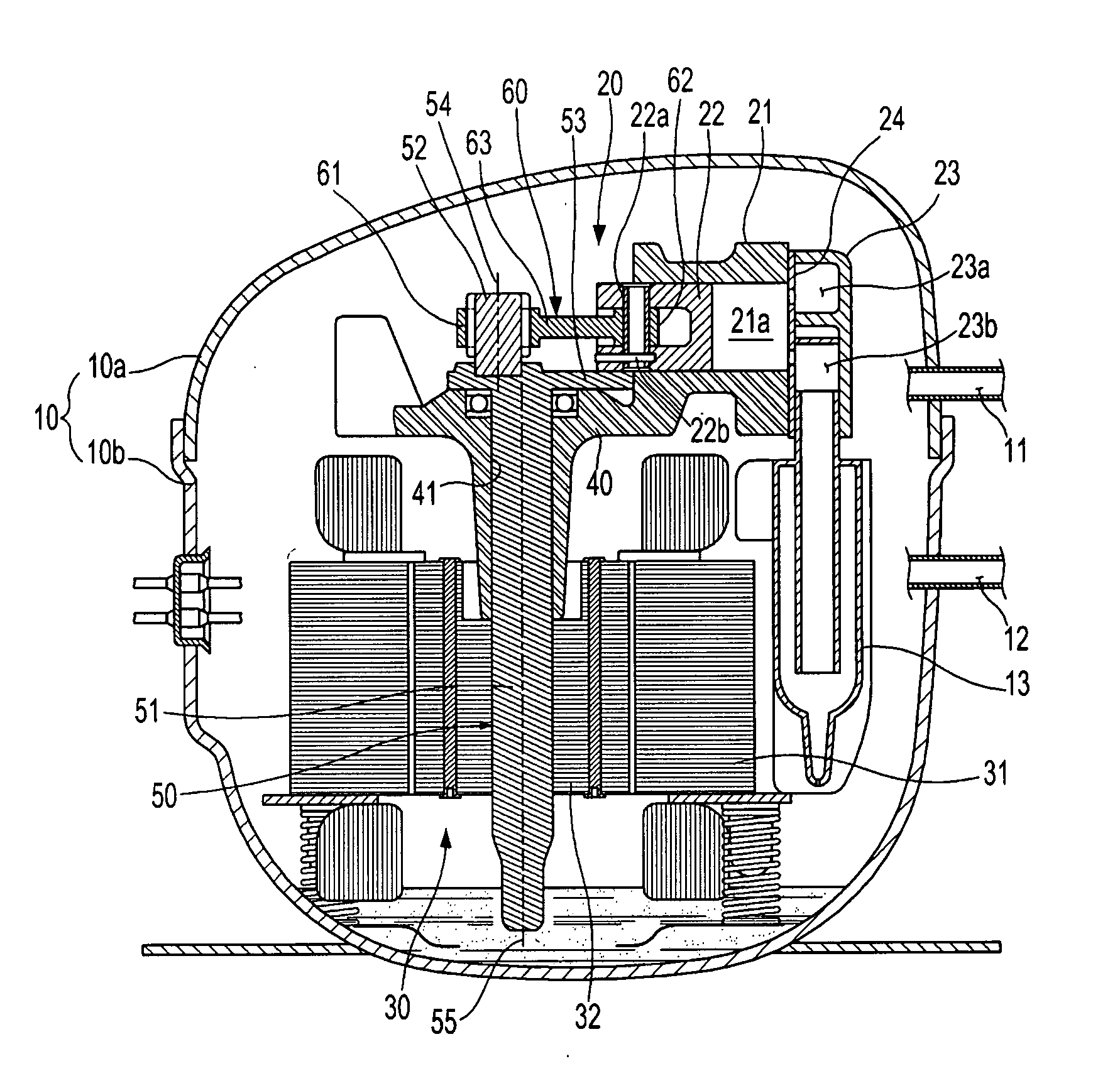
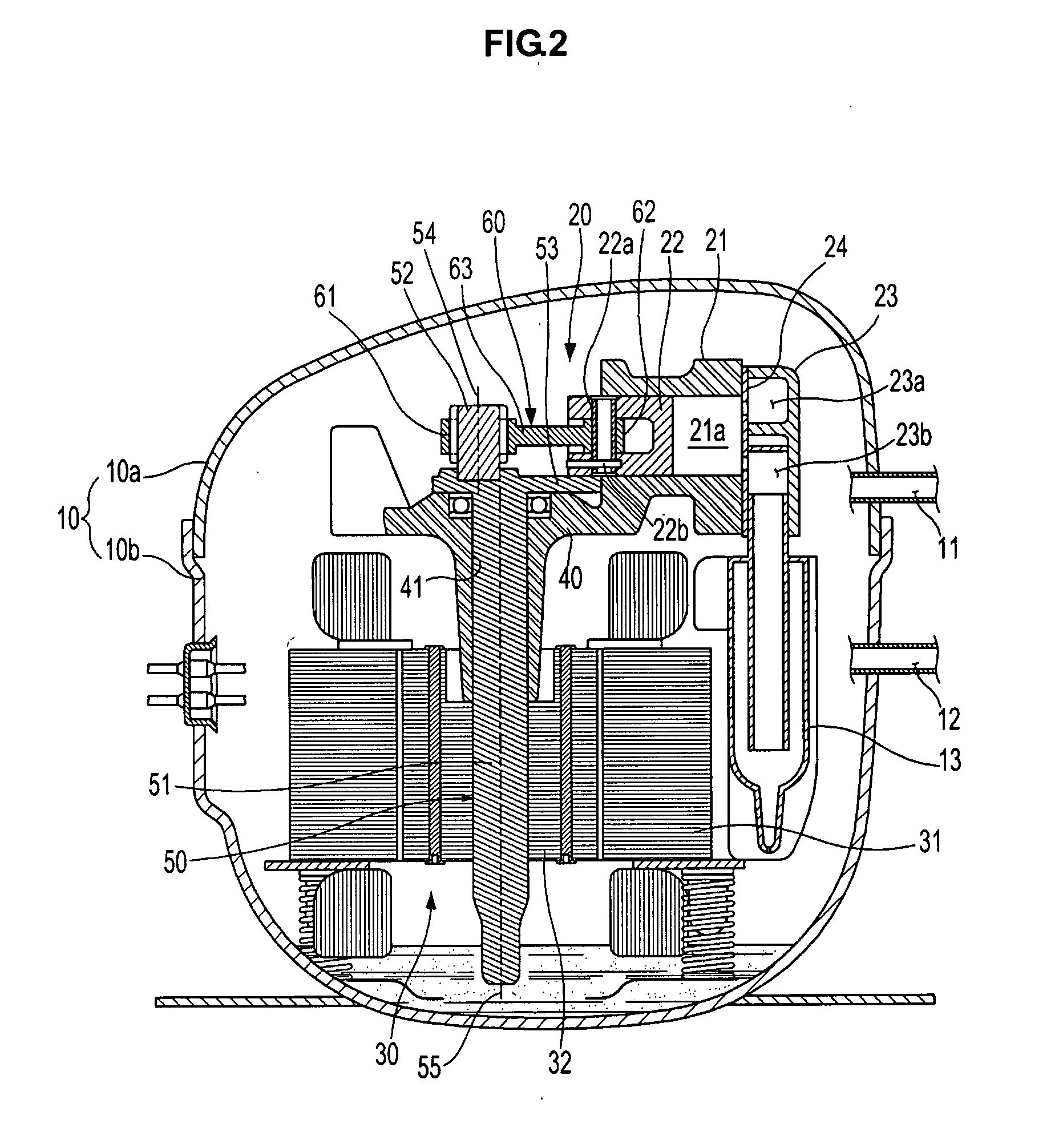
[0024]Reference will now be made in detail to a hermetic compressor consistent with an exemplary embodiment of the present invention, examples of which are illustrated in the accompanying drawings, wherein like reference numerals refer to like elements throughout. The embodiment is described below to explain the present invention by referring to the figures.

[0025]Referring to FIG. 2, the hermetic compressor according to an embodiment of the present invention generally includes a hermetic container 10 formed by coupling an upper container 10a and a lower container 10b to each other. The hermetic container 10 is provided with a suction pipe 11 for guiding a refrigerant from an external station into the hermetic container 10 and with a discharge pipe 12 for guiding the refrigerant, compressed within the hermetic container 10, to the outside of the hermetic container 10.

[0026]Provided within the hermetic container 10 are a compressing unit 20 to perform the compression of the refrigeran...


PUM


Abstract

A hermetic compressor with a connecting rod that can be assembled with a crankshaft and a piston while the piston is in a cylinder integrally formed with a frame. The hermetic compressor includes the frame formed with a hollow portion, a drive unit disposed on the frame, a cylinder integrally formed with the frame, the piston disposed within the cylinder, a crankshaft, and a connecting rod. The piston linearly reciprocates within the cylinder. The crankshaft has a main shaft portion adapted to rotate by a drive force of the drive unit, an eccentric shaft portion provided at one end of the main shaft portion, and a weight balance portion provided between the main shaft portion and the eccentric shaft portion. The main shaft portion is rotatably supported in the hollow portion. The eccentric shaft portion is positioned eccentrically relative to the main shaft portion. The weight portion is adapted to compensate for a rotating imbalance caused by the eccentric shaft portion. The eccentric shaft portion is fabricated separately from the crankshaft and rotatably coupled to the weight balance portion. The connecting rod couples the eccentric shaft portion and the piston. The connecting rod is formed to convert a rotating motion of the crankshaft into the linearly reciprocating motion of the piston.

Description

CROSS-REFERENCE TO RELATED APPLICATION[0001]This application claims the benefit of Korean Patent Application No. 2006-0096862, filed on Oct. 2, 2006 in the Korean Intellectual Property Office, the disclosure of which is incorporated herein by reference.FIELD OF THE INVENTION[0002]The present invention relates to a hermetic compressor, and, more particularly, to a hermetic compressor in which a piston, installed in a cylinder, can be easily assembled to a crankshaft via a connecting rod when the cylinder is integrally formed with a frame.BACKGROUND OF THE INVENTION[0003]In general, a hermetic compressor is employed in a refrigeration cycle of a refrigerator or air conditioner. As shown in FIG. 1, a conventional hermetic compressor includes a hermetic casing 1 forming an exterior of the compressor, a compressing unit 2 to perform the compression of a refrigerant within the hermetic casing 1, and a drive unit 3 to provide a compressive drive force required for the compression of the re...

Claims


Application Information

Patent Timeline
IPC IPC(8): F04B35/00F16C15/00F16H21/50
CPCF04B39/0022F04B39/0094F04B39/14Y10T74/2121Y10T74/211Y10T74/18032F16C3/10F04B39/00
Inventor RYU, RIO
Owner SAMSUNG GWANGJU ELECTRONICS CO LTD
Learn More