
Exhaust pipe structure improvement

Inactive Publication Date: 2008-04-03
LIU CHIN CHI
View PDF20 Cites 17 Cited by
  • Summary
  • Abstract
  • Description
  • Claims
  • Application Information

AI Technical Summary

Benefits of technology

[0006]It is a primary object of the present invention to provide an exhaust pipe structure improvement that has a heat-insulating block is disposed between a control device and an exhaust pipe for controlling the control device without easily being burnt out and effectively controlling exhaust volume of the exhaust pipe so as to increase practicability of the exhaust pipe.

Problems solved by technology

Although, some electronic controlled exhaust butterfly are used for these adjustment need, but the controller cannot be mounted onto the pipe itself because the heat generated by the exhaust will damage the motor very quickly.

Method used


Image

  • Exhaust pipe structure improvement
  • Exhaust pipe structure improvement
  • Exhaust pipe structure improvement

Examples


Embodiment Construction

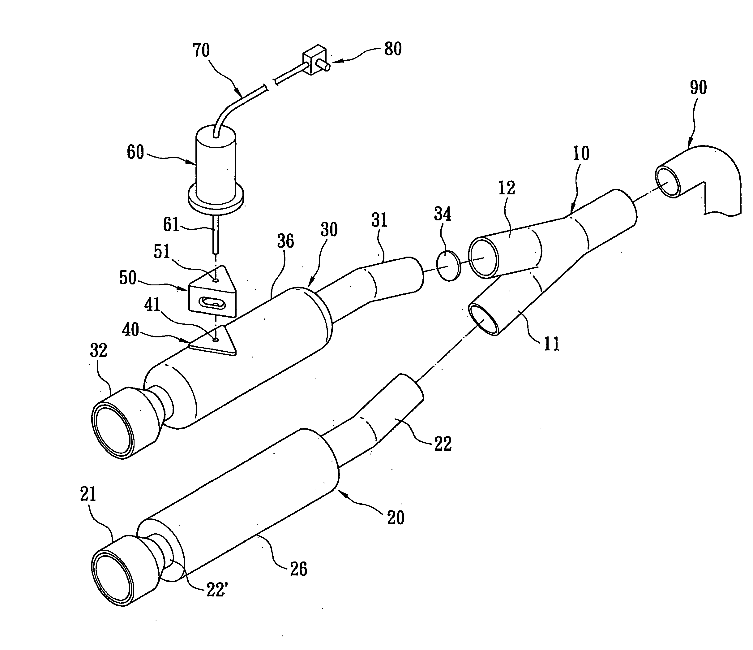
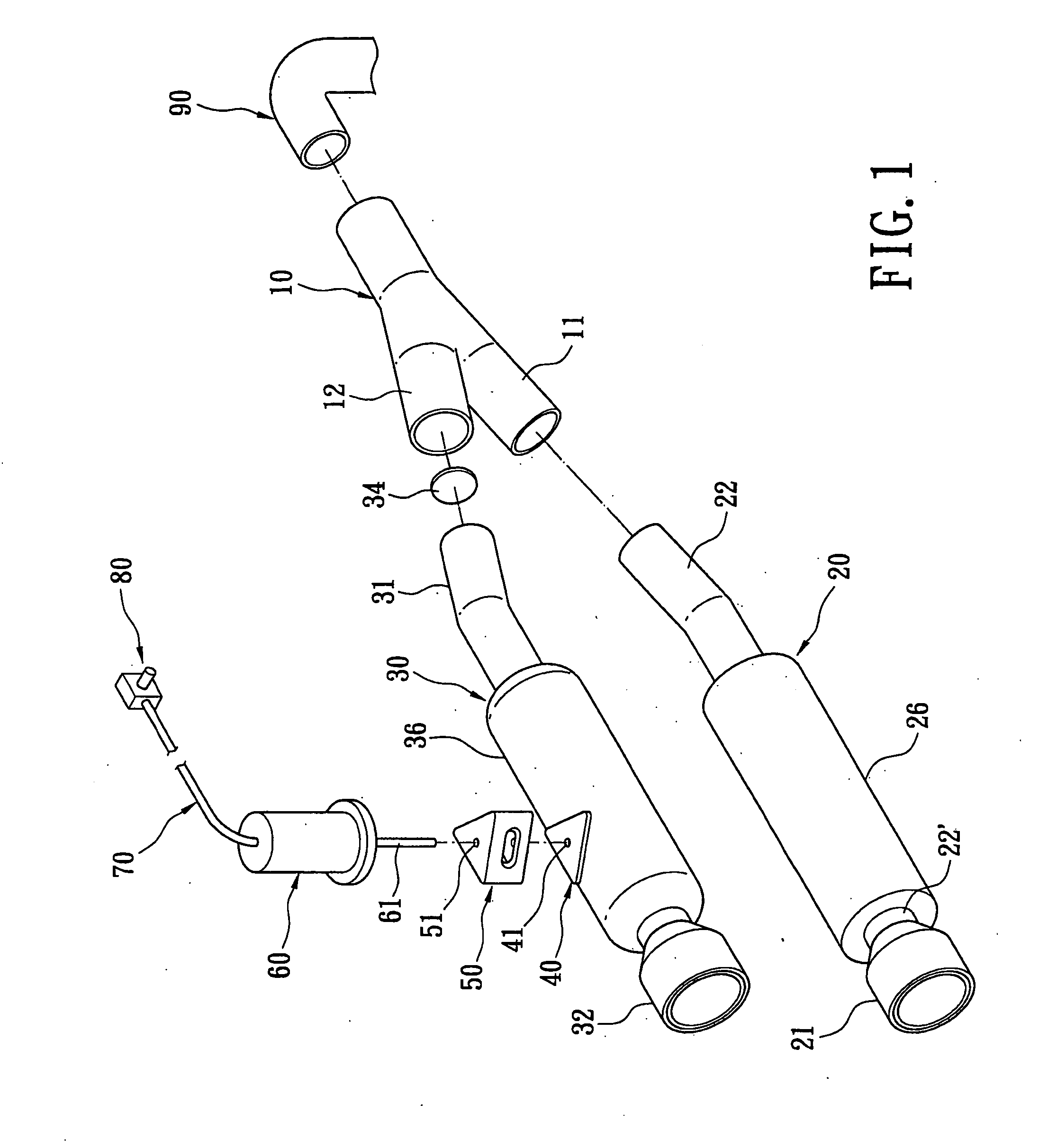
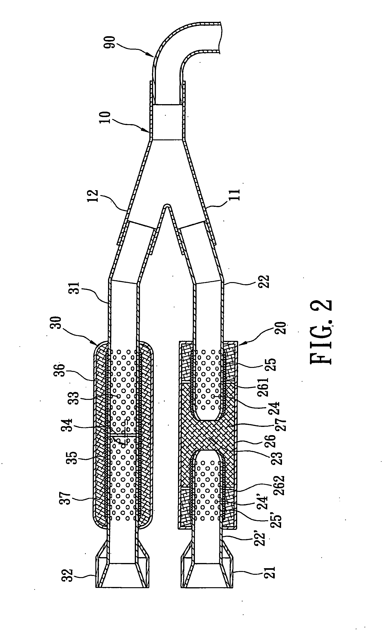
[0016]References are made to FIG. 1 and FIG. 2. An exhaust pipe structure improvement of the present invention is connected with a joint pipe 90 of an engine of a car, and comprises a bifurcation pipe 10, a first muffling pipe 20, a second muffling pipe 30, a placed base 40, a heat-insulating block 50 and a control device 60.

[0017]The bifurcation pipe 10 is a hollow pipe. One end of the bifurcation pipe 10 is divided into a first branch pipe 11 and a second branch pipe 12 and the other end is connected with the joint pipe 90 of the engine.

[0018]One end of the first muffling pipe 20 is connected with the first branch pipe 11 of the bifurcation pipe 10, and the other end thereof is sleeved by a tail pipe 21. The first muffling pipe 20 has two hollow pipe housings 22, and 22′, the two pipe housings 22, and 22′ are spaced at intervals and a flow region 23 is formed between the two pipe housings 22, and 22′. The two pipe housings 22, and 22′ have a plurality of muffling holes 24, and 24′...


PUM


Abstract

An exhaust pipe structure improvement includes a bifurcation pipe, a first muffling pipe, a second muffling pipe, a control device and a heat-insulating block. One end of the bifurcation pipe is divided into a first branch pipe and a second branch pipe, the first muffling pipe and the second muffling pipe are separately connected with the first branch pipe and the second branch pipe of the bifurcation pipe, the second muffling pipe has a valve piece therein. The control device is installed on one side of the second muffling pipe for controlling the valve piece to open or close an exhaust section of the second muffling pipe, and the heat-insulating block is clipped between the control device and the second muffling pipe for controlling the control device without easily being burnt out and effectively controlling exhaust volume of the exhaust pipe so as to increase practicability of the exhaust pipe.

Description

BACKGROUND OF THE INVENTION[0001]1. Field of the Invention[0002]The present invention relates to an exhaust pipe structure improvement, and more particularly to an exhaust pipe structure improvement has a control device installed on the exhaust pipe, which can adjust the volume of exhaust and sound according to different road situations.[0003]2. Description of the Prior Art[0004]A car is a kind of common means of transportation in the present day, and there are different traffic regulations of noise and pollution from cars and speed of driving in an urban district or in a suburban district. Besides, user's requires for horsepower of cars are related to an exhaust volume of exhaust pipes. For example, when the cars are driven on climbing road sections or in the suburban areas, the air volume of the exhaust pipe must be increased to cope with the promotion of the horsepower and acceleration. Furthermore, there is request of low noise and low pollution, when the cars are driving in the...

Claims


Application Information

Patent Timeline
IPC IPC(8): F01N1/16F01N7/00
CPCF01N1/16F01N1/24F01N13/011F01N2410/00F01N2470/00F01N13/08
Inventor LIU, CHIN-CHI
Owner LIU CHIN CHI
Learn More