
Head slider having protruding head element and apparatus for determining protrusion amount of head element

a head element and slider technology, applied in the direction of maintaining head carrier alignment, recording information storage, instruments, etc., can solve the problem of expanding the insulating non-magnetic film, and achieve the effect of reliable avoidance of damage to the head elemen

Inactive Publication Date: 2008-03-27
FUJITSU LTD
View PDF1 Cites 0 Cited by
  • Summary
  • Abstract
  • Description
  • Claims
  • Application Information

AI Technical Summary

Benefits of technology

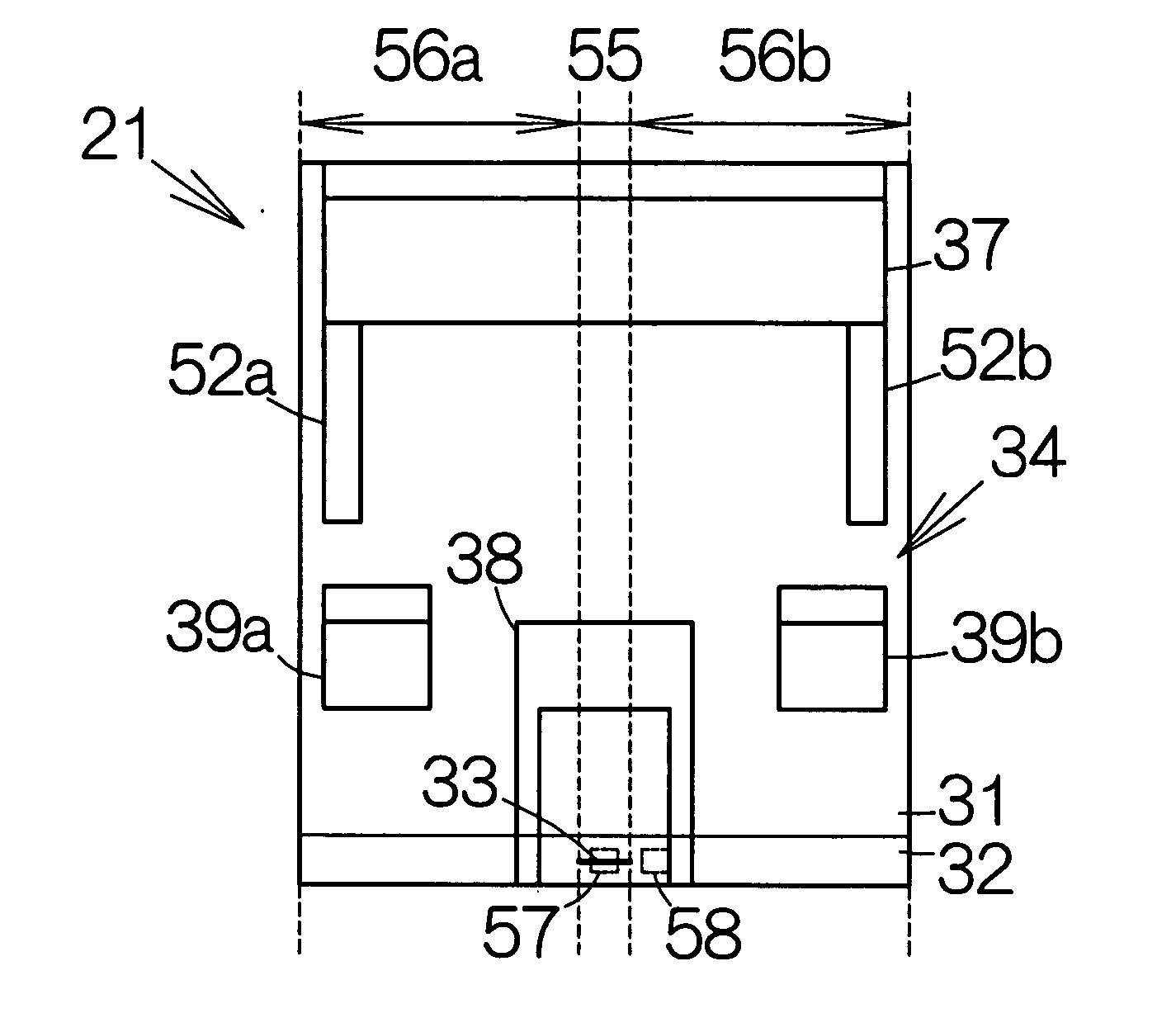
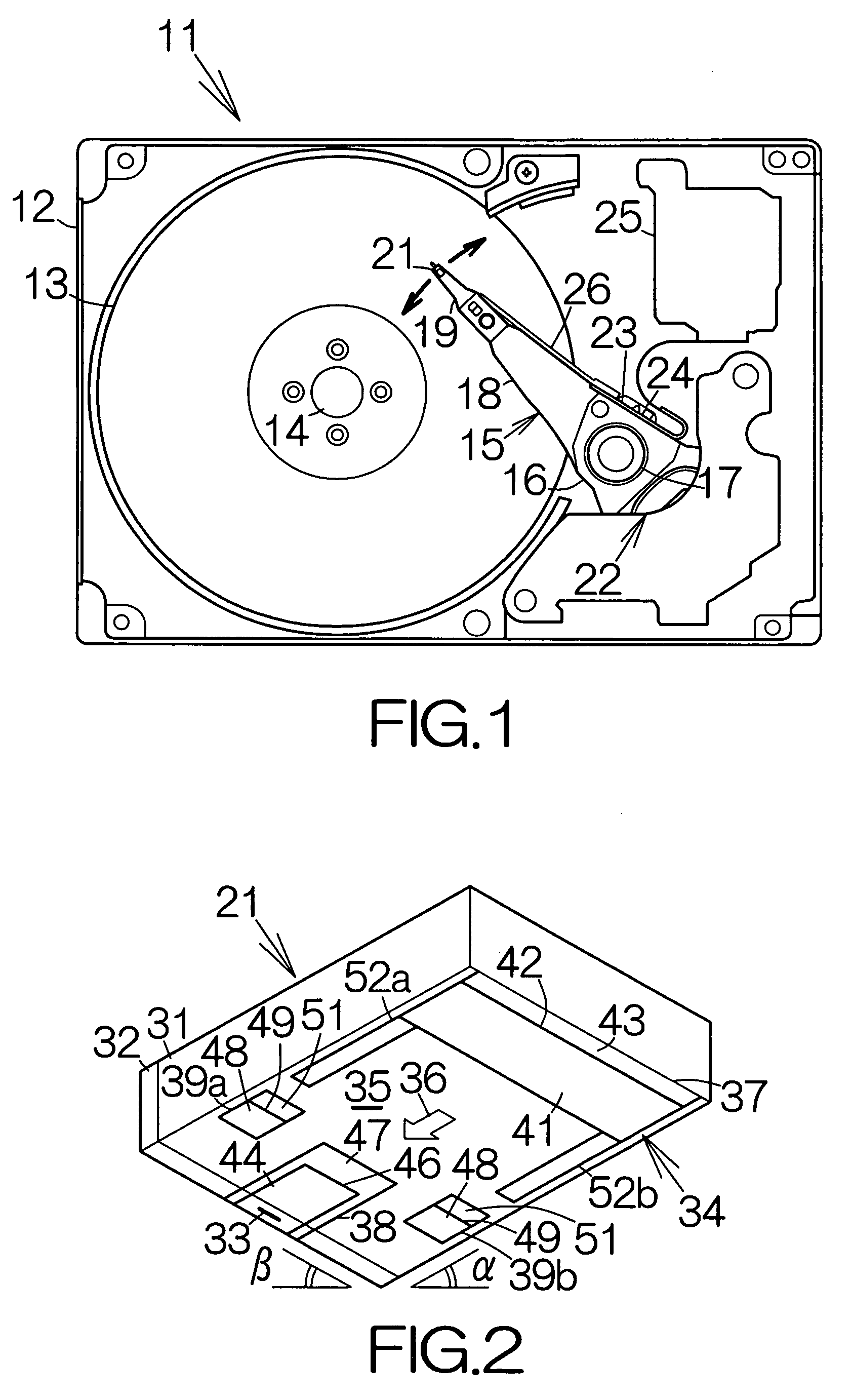
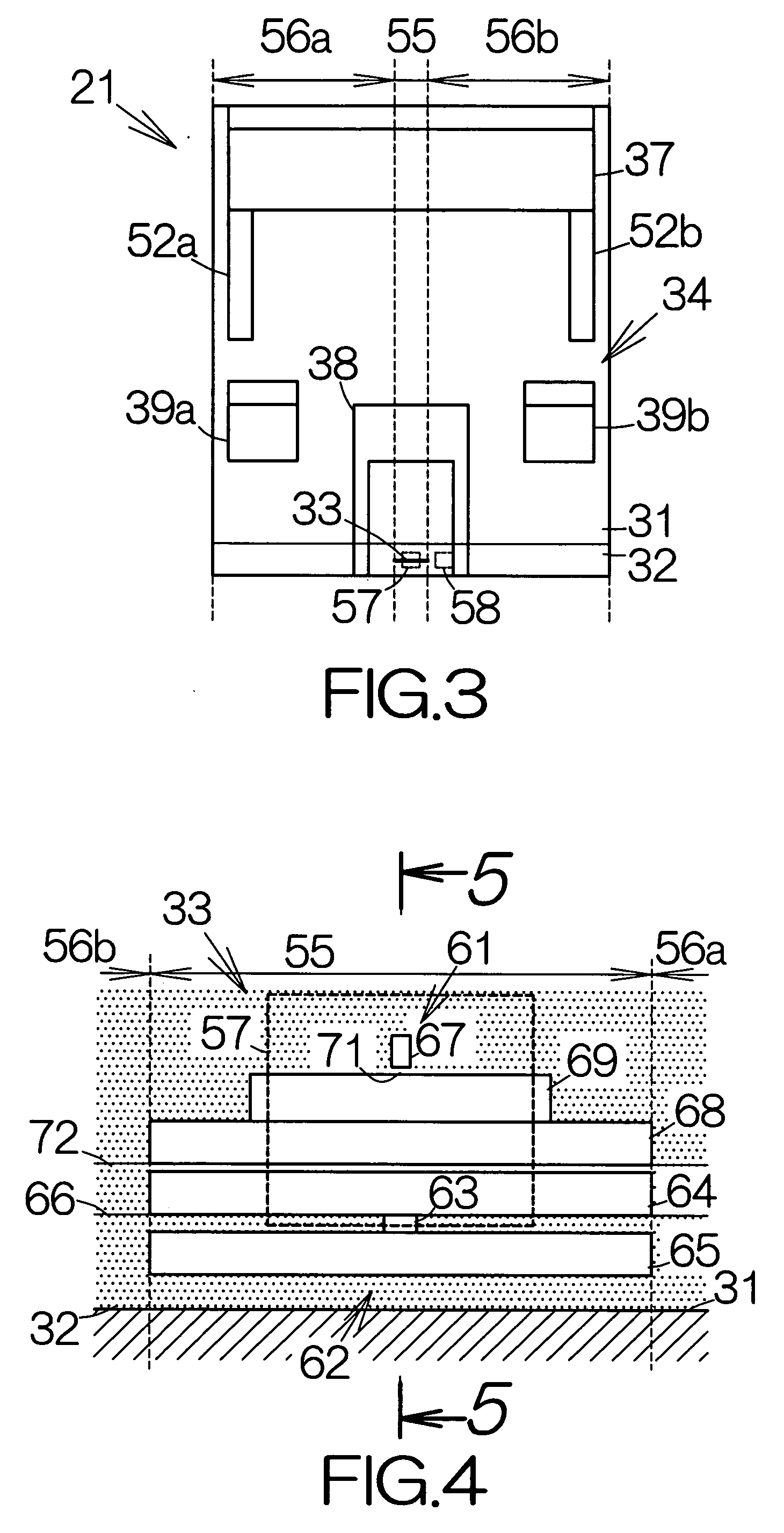
The present invention provides a head slider and a storage medium drive that can determine the protrusion amount of a head element without inducing any damages to the head element. The head slider has a slider body with a medium-opposed surface, an insulating non-magnetic film overlaid on the outflow end surface of the slider body, and a first actuator embedded in the insulating non-magnetic film in the first area, causing the first section of the insulating non-magnetic film to protrude. The head slider also has a second actuator embedded in the insulating non-magnetic film in the second area, causing the second section of the insulating non-magnetic film to protrude. The first actuator causes the first section of the insulating non-magnetic film to protrude during a zero calibration, while the second actuator causes the second section of the insulating non-magnetic film to protrude during a contact between the non-magnetic film and the storage medium. The determination apparatus includes a controlling section, a detection section, and a determination section. The technical effects of the present invention are that it provides a reliable way to determine the protrusion amount of a head element without inducing any damages, and it ensures the accuracy of the flying height of the head element.

Problems solved by technology

This results in expansion of the insulating non-magnetic film at a position adjacent to the heating wiring patterns.

Method used


Image

  • Head slider having protruding head element and apparatus for determining protrusion amount of head element
  • Head slider having protruding head element and apparatus for determining protrusion amount of head element
  • Head slider having protruding head element and apparatus for determining protrusion amount of head element

Examples


Embodiment Construction

[0026]FIG. 1 schematically illustrates the structure of a hard disk drive, HDD, 11 as an example of a storage medium drive or a storage device according to the present invention. The hard disk drive 11 includes a box-shaped enclosure body 12 defining an inner space in the form of a flat parallelepiped, for example. The enclosure body 12 may be made of a metallic material such as aluminum, for example. Molding process may be employed to form the enclosure body 12. An enclosure cover, not shown, is coupled to the enclosure body 12. An inner space is defined between the enclosure body 12 and the enclosure cover. Pressing process may be employed to form the enclosure cover out of a plate material, for example. The enclosure body 12 and the enclosure cover in combination establish an enclosure.

[0027]At least one magnetic recording disk 13 as a storage medium is enclosed in the enclosure body 12. The magnetic recording disk or disks 13 are mounted on the driving shaft of a spindle motor 1...


PUM

PropertyMeasurementUnit
flying heightaaaaaaaaaa
width L1aaaaaaaaaa

Abstract

A head slider has a medium-opposed surface defining first and second areas extending side by side from the inflow end to the outflow end. A head element is embedded in an insulating non-magnetic film. The head element at least locates a write gap in a first section defined in the insulating non-magnetic film in the first area. A first actuator is embedded in the insulating non-magnetic film in the first area. The first actuator causes the first section to protrude. A second actuator is embedded in the insulating non-magnetic film in the second area. The second actuator causes a second section of the insulating non-magnetic film to protrude. The second section is utilized in a so-called zero calibration. The first section and the head element are prevented from protruding during the zero calibration. This results in are liable avoidance of damage to the head element.

Description

BACKGROUND OF THE INVENTION[0001]1. Field of the Invention[0002]The present invention relates to ahead slider incorporated in a storage medium drive such as a hard disk drive, HDD.[0003]2. Description of the Prior Art[0004]A head slider including an actuator for driving a head element is well known. An insulating non-magnetic film is overlaid on the outflow end surface of a slider body in the head slider. Ahead element is embedded within the non-magnetic film. A heating wiring pattern is embedded in the head element. The heating wiring pattern generates heat in response to the supply of electric current. The head element is allowed to get closer to a magnetic recording disk with the assistance of expansion of the insulating non-magnetic film.[0005]When the head sliders are incorporated in hard disk drives, the head sliders suffer from dispersion of the flying height in a range between 2 nm and 3 nm approximately. A so-called zero calibration is effected to correct the flying height....

Claims


Application Information

Patent Timeline
Patent Type & Authority Applications(United States)
IPC IPC(8): G11B5/60
CPCG11B5/3133G11B5/3136G11B5/6064G11B5/581G11B5/6011G11B5/5534
Inventor TAKAHASHI, SHINICHI
Owner FUJITSU LTD
Learn More