Rotation angle detecting device
a detection device and rotating angle technology, applied in galvano-magnetic devices, instruments, galvano-magnetic hall-effect devices, etc., can solve problems such as affecting the accuracy of rotation angle measurement, and achieve the effect of high speed
- Summary
- Abstract
- Description
- Claims
- Application Information
AI Technical Summary
Benefits of technology
Problems solved by technology
Method used
Image

Examples
first embodiment
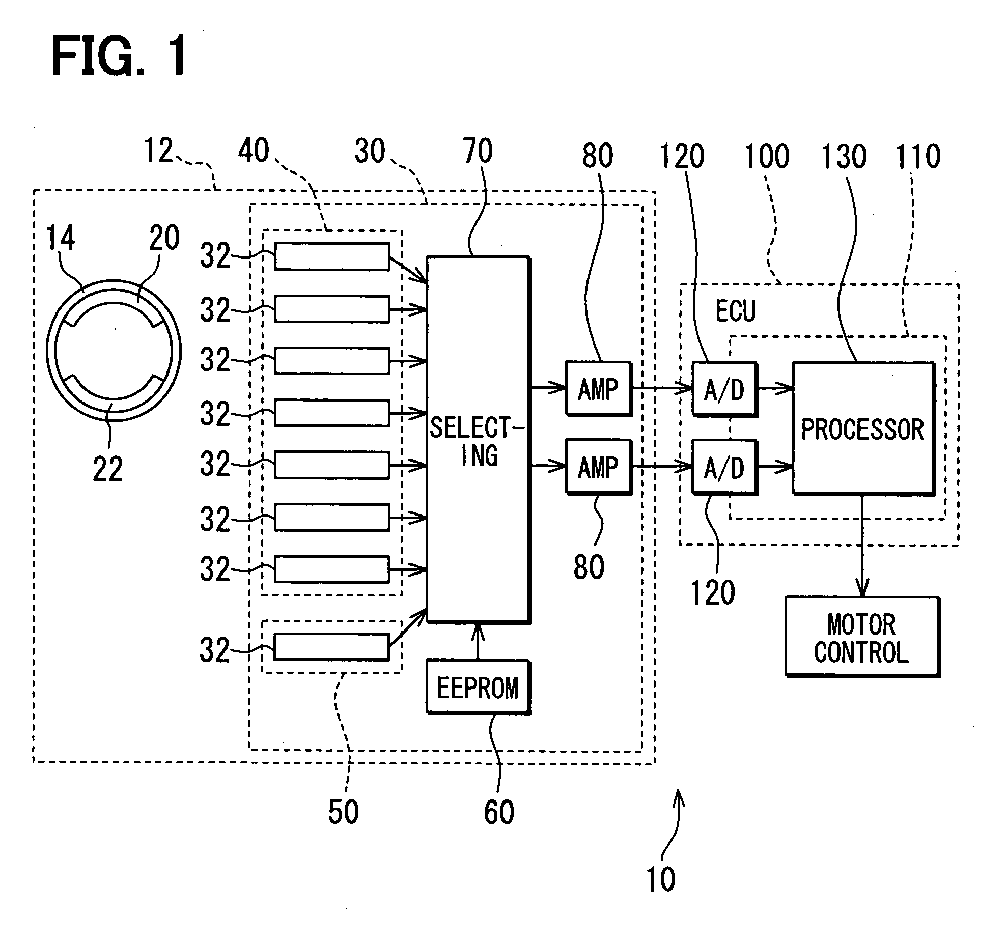
[0029]A rotation angle control system according to the invention will be described with reference to FIGS. 1-3.
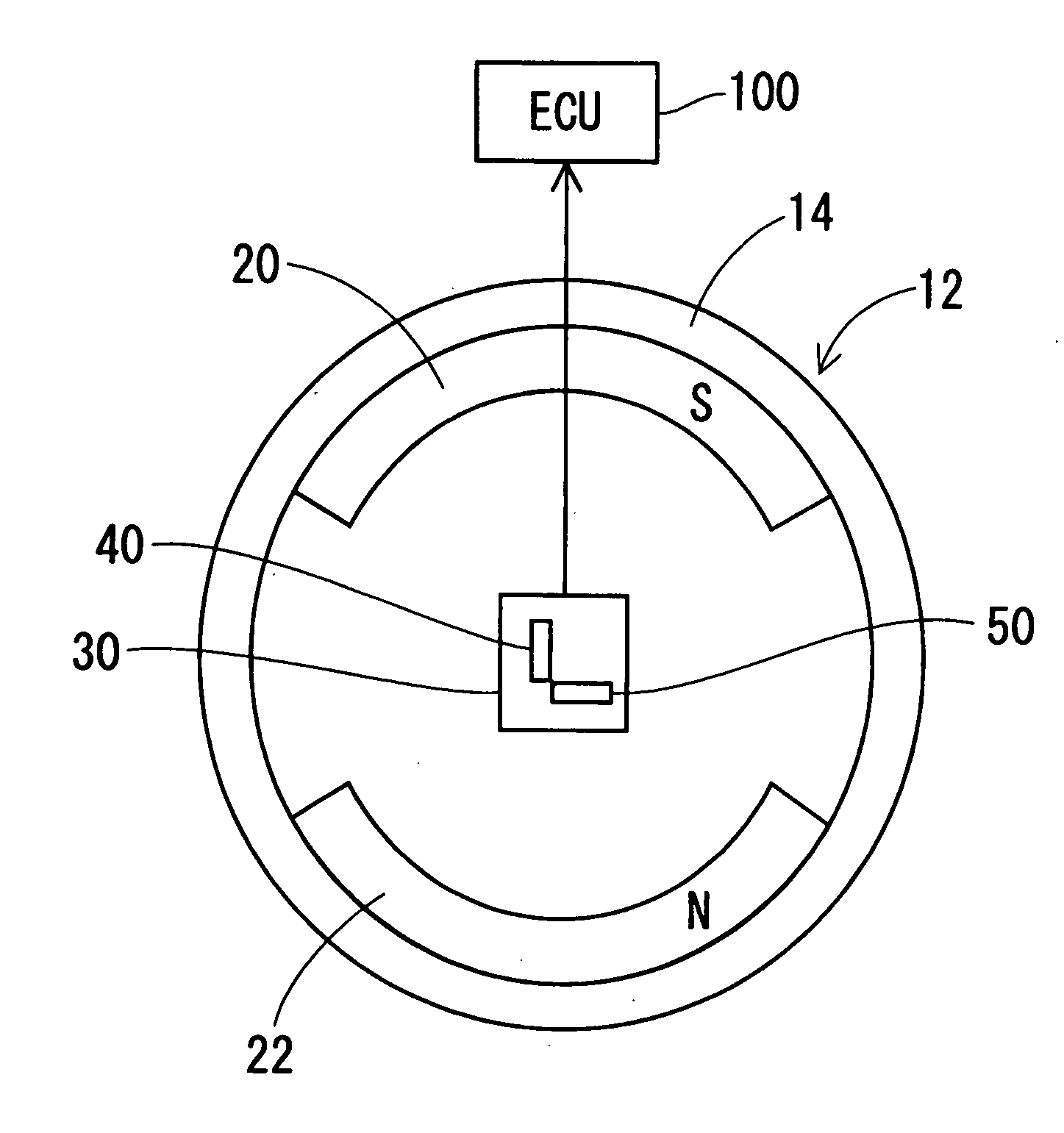
[0030]The rotation angle control system 10 includes a rotation angle detecting device 12, a Hall IC 30 and an ECU 100. The rotation angle detecting device 12 includes a yoke 14, a pair of arc-shaped permanent magnets 20, 22 and the IC 30. The yoke 14 is a cylindrical magnetic member that is rotated by a rotating object such as a rotary shaft of an electric motor. The permanent magnets 20, 22 are arc-shaped members fixed to the inner cylindrical surface of the yoke 14 at an interval of 180 degrees in angle from each other. The permanent magnets 20, 22 are magnetized in a radial direction to form a generally parallel magnetic field that extends in the radial direction. In other words, the permanent magnet 20 is magnetized to have a magnetic pole (e.g. S-pole) different from the magnetic pole (e.g. N-pole) of the permanent magnet 22 at the surfaces thereof facing each other.
[0...
second embodiment
[0040]A rotation angle detecting device according to the invention will be described with reference to FIG. 4.
[0041]Incidentally, the same reference numeral represents the same or substantially the same part, portion or component as the preceding embodiment hereafter.
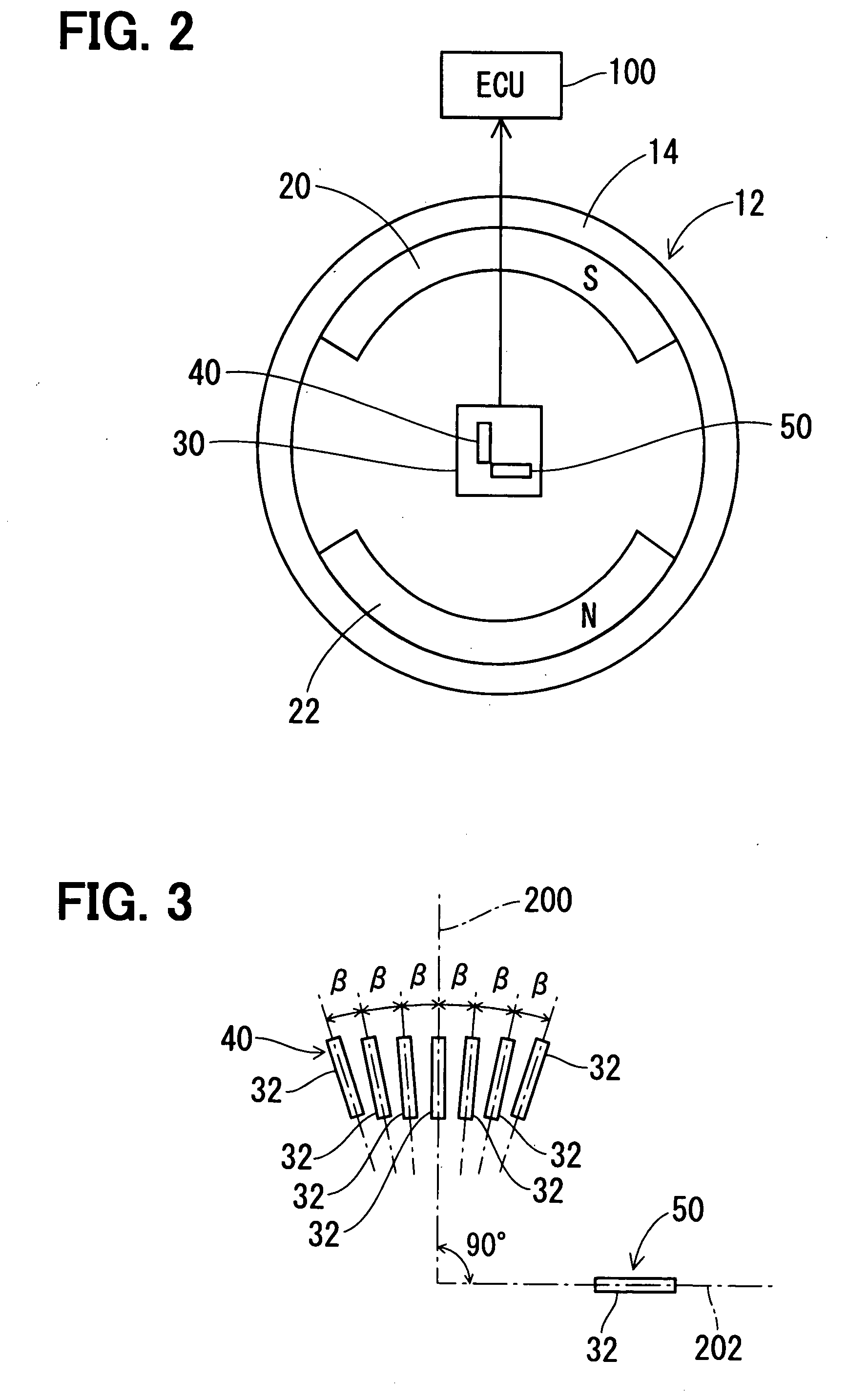
[0042]In addition to plural (e.g. seven) Hall elements 32 of the first sensing section 40 that are formed in a circumferential direction of the cylindrical yoke 14, plural (e.g. four) Hall elements 32 of the second sensing section 50 are formed in the direction parallel to the base line so that the sensing surfaces thereof respectively face in directions different from one another by an angle of β (e.g. 0.1°), while the sensing element 32 positioned on the second base line 202 so that the sensing surface thereof faces in the direction parallel with the first base line 200.
third embodiment
[0043]A rotation angle detecting device according to the invention will be described with reference to FIG. 5.
[0044]The plural (e.g. seven) Hall elements 32 of the first sensing section 40 that are formed in a circumferential direction of the cylindrical yoke 14 so that the sensing surfaces thereof respectively face in directions different from one another by an angle of β1(e.g. 1°), and the plural (e.g. seven) Hall elements 32 of the second sensing section 50 are formed in the direction parallel to the first base line 200 so that the sensing surfaces thereof respectively face in directions different from one another by an angle of β (e.g. 0.1°).
[0045]In the second and third embodiment, the phase difference between the output signals of the first and second sensing sections 40, 50 can be adjusted at a higher accuracy than the first embodiment.
PUM
 Abstract
Description
Claims
Application Information
 - R&D
- Intellectual Property
- Life Sciences
- Materials
- Tech Scout
- Unparalleled Data Quality
- Higher Quality Content
- 60% Fewer Hallucinations
Browse by: Latest US Patents, China's latest patents, Technical Efficacy Thesaurus, Application Domain, Technology Topic, Popular Technical Reports.
© 2025 PatSnap. All rights reserved.Legal|Privacy policy|Modern Slavery Act Transparency Statement|Sitemap|About US| Contact US: help@patsnap.com