
Beverage Mug

a beverage mug and mug body technology, applied in the field of beverage mugs, can solve the problems of beverage spilling out, beverage stains the table or surrounding objects, beverage remains small, etc., to achieve the effect of avoiding additional parts and manipulation, increasing the speed of liquid flow, and avoiding beverage spilling ou

Inactive Publication Date: 2008-03-27
OLEGOVICH MAGAS JAROSLAV
View PDF4 Cites 1 Cited by
  • Summary
  • Abstract
  • Description
  • Claims
  • Application Information

AI Technical Summary

Benefits of technology

[0006] It is an object of the present invention to modernize the mug with a chute and a storage chamber / attachment by modification of the shape of the elements and their location, increasing the speed of the liquid flow in the chute, making washing of the attachment easier, avoiding additional parts and manipulations, and achieving maximum compactness without downsizing the attachment, thus, increasing the efficiency of the mug, improving its ergonomic properties, comfort and practicability, and simplifying the manufacturing process.
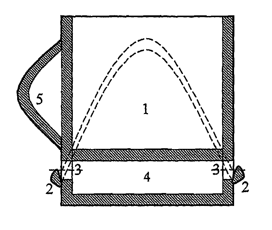
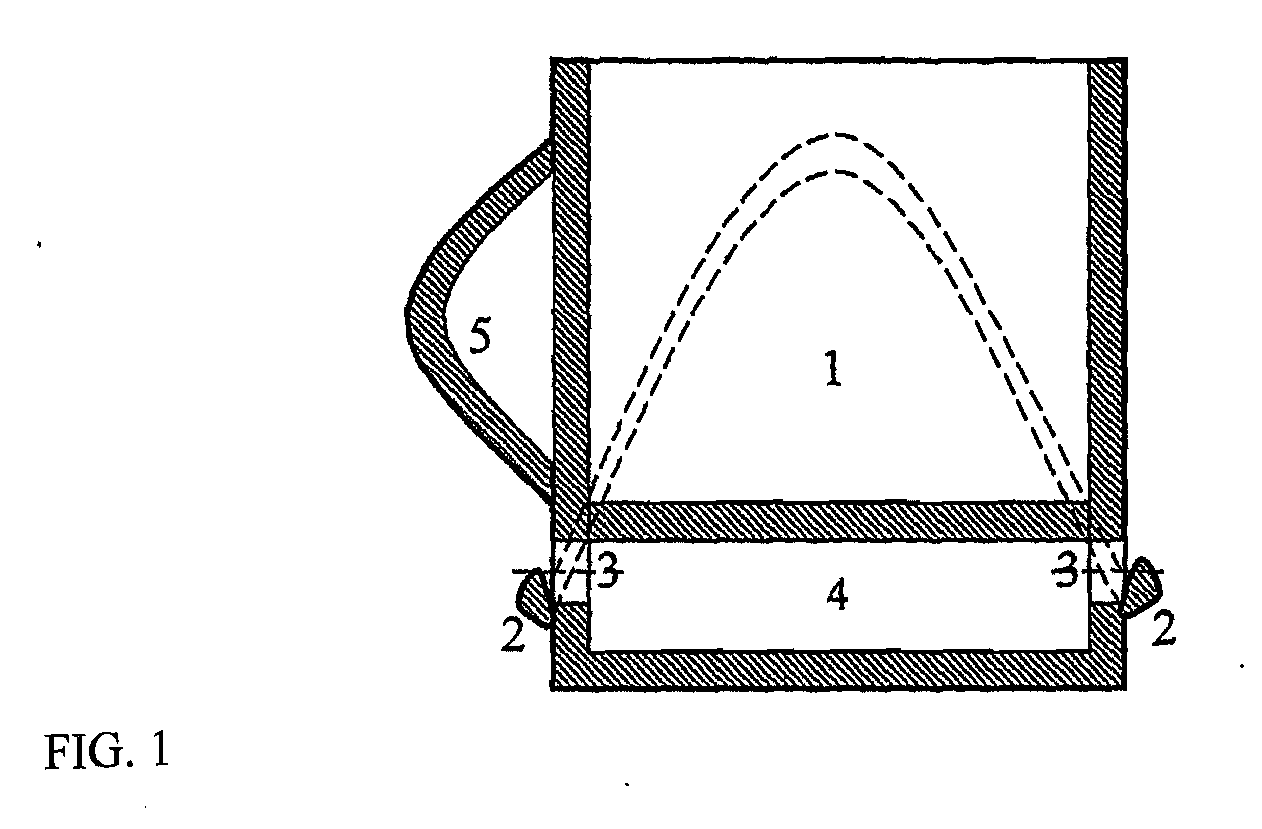
[0008] This chute, with two upper and two lower points, has bigger tilt angles providing for higher speed of the liquid flow to the storage chamber. For that reason, the spillage does not stay in the catch flow and cannot splash on the surrounding objects when the mug is tilted during drinking. The higher speed of the liquid flow provides for the smaller depth and width of the chute. The location of the storage chamber under the main container provides for the improved compactness of the beverage mug—one body consisting of two chambers, preservation of the usual look and esthetics of the mug, variation of the size of the storage chamber without changing the mug's horizontal dimensions (body diameter). The body of the mug can be cylindrical, enabling manufacturing with moulds and standard equipment. Availability of two opposite drain holes eases washing of the added container with water.

Problems solved by technology

The shortcoming of the known cups is that when handled without caution, they stain the table or surrounding objects.
When the beverage is poured or stirred with the spoon, when sugar is added or the mug is shaken, the beverage spills out, flows down the outer walls and stains the surrounding objects.
However, when the cup is lifted from the saucer, a small amount of beverage remains on the bottom of the cup.
This beverage can make a drop and stain the surrounding objects, e.g. clothes.
In the business setting beverages are consumed during phone conversations and work on a computer, thus making using the saucer inconvenient (because both arms must be free).
The shortcoming of the given construction is that this attachment has a very complex form, making the after-use washing impossible (it is very difficult to wash the attachment with water and clean the residue, while after washing it is impossible to pour out a large amount of liquid that stays in the attachment with drink residue).
Another imperfection of this solution is its bigger size and weight of the beverage cup, which negatively affects ease of use and esthetics of the cup.
One of the shortcomings of this mug is a small tilt angle of the chute not providing for safe direction of liquid to the storage chamber when the position of the mug is not vertical.
Owning to the small tilt angle, the speed of liquid flow down the chute is low, which increases the probability of the splashing and staining the surrounding objects when the mug is tilted during drinking.
The size of the storage chamber is too small, and only a small amount of liquid can be collected (low capacity).
Washing the storage chamber is rather difficult and is only possible when the drainer is open.
Drain and special mug require additional manipulations, which is uncomfortable and impractical.
During use, the mug can depressurize, and that loss of pressure will make further use of the mug impossible.
Its shape and lateral location of the storage chamber complicate the manufacturing process, because principally new techniques and equipment are needed.
Additional elements (hermetic cap) increase the cost of the product.

Method used


Image

  • Beverage Mug
  • Beverage Mug
  • Beverage Mug

Examples


Embodiment Construction

[0030] According to the invention (FIG. 1, FIG. 2), a beverage mug with a handle is supplemented by a drip catch storage 4 chamber located below a main 1 container and made as a double bottom. The bottom of the main container can be both flat and spherical (FIG. 3). A spherical bottom provides for an increased diameter of the drain holes and placing them higher without increasing the area of the storage chamber, thus without decreasing the volume of the main container. At its rear, the storage 4 chamber has either one or two diametrically opposed drain holes 3 (FIG. 1, FIG. 2). In order to keep the storage chamber free of insects, the drain hole (holes) can be supplemented by metal or polymeric nets. The invention contemplates an embodiment where the drain hole (holes) are substituted by the cluster (clusters) of drain holes (FIG. 15) consisting of the minimum two-six smaller drain holes. In the embodiment with two diametrically opposed holes, a handle is located above one of the dr...


PUM


Abstract

The invention is a beverage mug with a storage chamber for spillage. Its scope of use is public catering, including transport catering, pottery for general use. The beverage mug comprises the walls, a bottom, and a handle wherein there is a storage chamber for collecting the spillage, a chute on the outer surface for diverting the spillage to the storage chamber. The present invention is a beverage mug with a lower probability of spillage and staining of the surrounding objects resulting from abrupt and incautious movements and pounding with no need of a saucer.

Description

RELATED APPLICATIONS [0001] This application is a continuation application of International Application PCT / UA2006 / 000010 filed on Mar. 6, 2006, which, in turn, claims priority to Ukrainian Patent Application No. u200505282 filed on Jun. 3, 2005, which is incorporated herein by reference in its entirety.BACKGROUND OF THE INVENTION [0002] The instant invention relates to pottery and can be used in public catering, and more specifically in transport catering. [0003] Cups and mugs provided in the known art consist of the walls hermetically integral with the bottom and a handle on the outer surface of the walls (as in a promotional leaflet of bouillon cubes “Maggi” Hot Cup 2004). The shortcoming of the known cups is that when handled without caution, they stain the table or surrounding objects. When the beverage is poured or stirred with the spoon, when sugar is added or the mug is shaken, the beverage spills out, flows down the outer walls and stains the surrounding objects. In order t...

Claims


Application Information

Patent Timeline
Patent Type & Authority Applications(United States)
IPC IPC(8): F17C13/00A47G19/22B65D1/34
CPCA47G19/22A47G19/145
Inventor OLEGOVICH, MAGAS JAROSLAV
Owner OLEGOVICH MAGAS JAROSLAV
Learn More