
Electronic keyboard instrument

a keyboard instrument and keyboard technology, applied in the field of electronic keyboard instruments, can solve the problems of difficult to extend the output frequency band to a lower frequency range, difficult to secure a space, and difficult to spread sound well, and achieve the effect of easy formation

Active Publication Date: 2008-03-27
YAMAHA CORP
View PDF35 Cites 28 Cited by
  • Summary
  • Abstract
  • Description
  • Claims
  • Application Information

AI Technical Summary

Benefits of technology

[0021]Because the upper case has a surface area large enough to form a plurality of small sound emitting holes or to form one large sound emitting hole, sound passages through which an acoustic wave can smoothly pass can be easily formed.
[0048]The electric circuit part necessary for driving the electroacoustic transducer can be efficiently accommodated in a space between the keyboard and the bottom plate of the lower case in case that the mass bodies are not used or in a space between the mass bodies and the bottom plate of the lower case in case that the mass bodies are used, whereby the outer size of the electronic keyboard instrument can be made compact.

Problems solved by technology

Particularly, in the piano-type keyboard instrument provided with a hammer (mass body), because a mass body pivoting mechanism has large bulk, it is more difficult to secure a space.
It is preferable to reduce a size of the speaker unit itself, however it is difficult to extend an output frequency band to a lower frequency range.
However, when the electronic keyboard instrument is placed on a desk, the sound is not spread well.
To this end, in practical, the speaker unit cannot help being adopted to a cabinet type electronic keyboard instrument which has a sound emitting space below the speaker unit.
However, because this electronic keyboard instrument is also a cabinet type, it has a large size.

Method used


Image

  • Electronic keyboard instrument
  • Electronic keyboard instrument
  • Electronic keyboard instrument

Examples


first embodiment

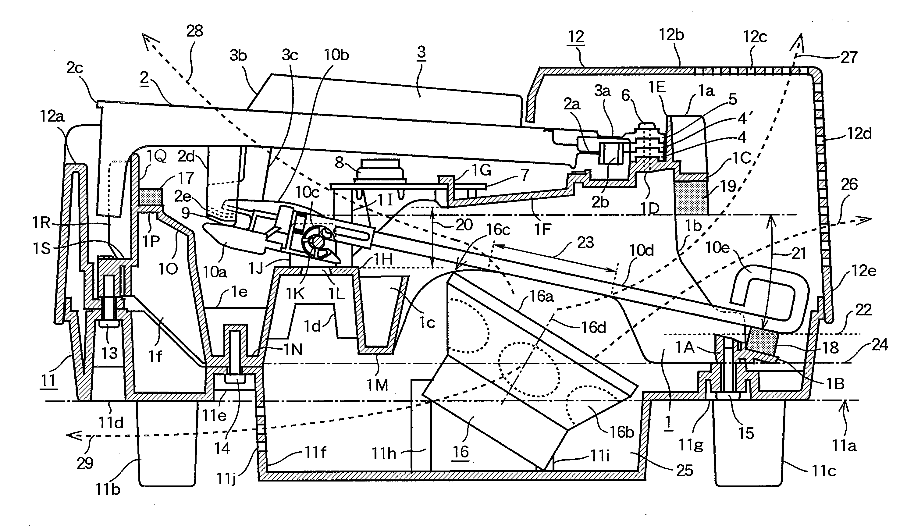
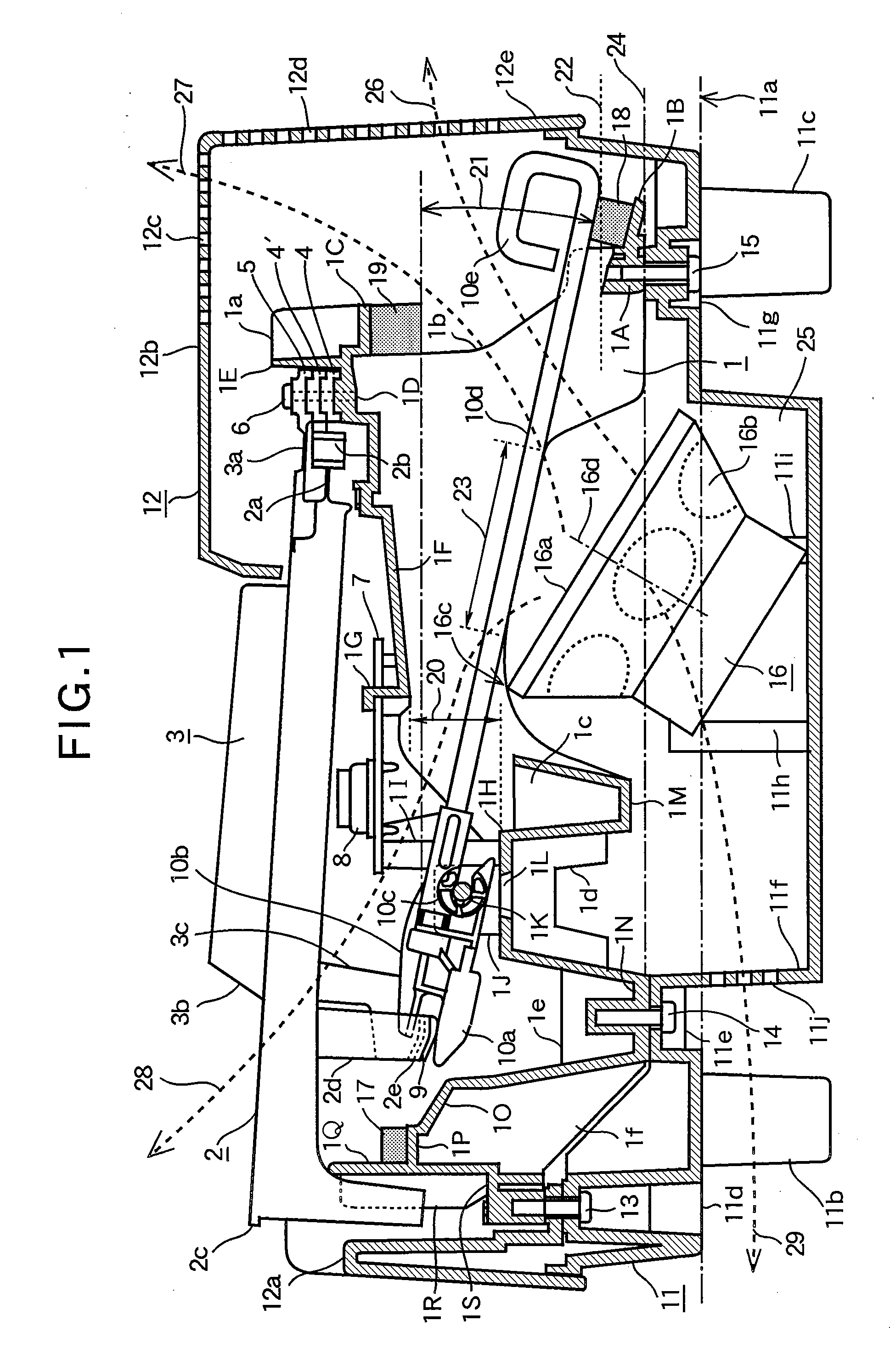
[0058]FIG. 1 is an explanation view illustrating the present invention, and a schematic sectional view when seeing an electronic keyboard instrument from the right side. In order to show coupling relations between respective components, the respective parts are sectioned on different planes.

[0059]Hereinafter, in a longitudinal direction of a key, a depth direction will be referred to as a “rear direction”, and a direction directed to a front end of the key will be referred to as a “front direction”. A direction in which the keys are arranged parallel in the keyboard will be referred to as a “key arranging direction” or simply “width direction”.

[0060]The keyboard is provided with a plurality of keys composed of key body parts (white keys) 2 and key body parts (black keys) 3, which are partially illustrated in the drawing. Each of the keys is pivotably supported by a keyboard frame (supporting member or frame member) 1.

[0061]The keyboard frame 1 is unitarily made of resin, however it ...

second embodiment

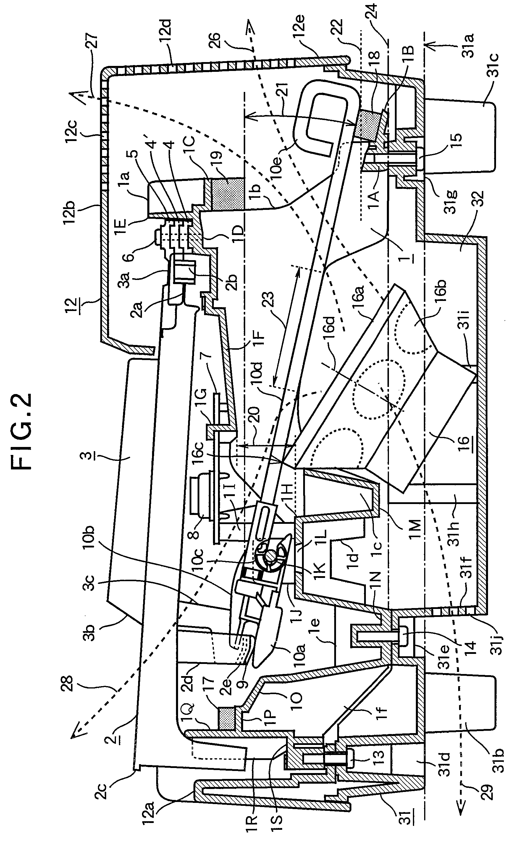
[0128]FIG. 2 is an explanation view illustrating the present invention. Similarly to FIG. 1, FIG. 2 is a schematic sectional view when seeing an electronic keyboard instrument from the right side. The respective parts are sectioned on different planes. The same parts as shown in FIG. 1 are denoted by the same reference numerals.

[0129]This embodiment has a difference in the arrangement of the speaker unit 16 from the embodiment shown in FIG. 1.

[0130]In also this embodiment, the mass body pivot supporting part 1J is mounted such that the pivot point part 10c is positioned higher than the lowermost descending position 22 when the inertia generating part 10d of the mass body 10 pivots to the lower limit position. The speaker unit 16 is accommodated in the space below the inertia generating part 10d, such that the uppermost portion 16c of the speaker unit 16 is positioned higher than the lowermost descending position 22 of the inertia generating part 10d.

[0131]Moreover, the upper end (u...

third embodiment

[0145]FIG. 4 is an explanation view illustrating the present invention. Similarly to FIG. 1, FIG. 4 is a schematic sectional view when seeing an electronic keyboard instrument from the right side. The respective parts are sectioned on different planes.

[0146]The same parts as shown in FIG. 1 are denoted by the same reference numerals. This embodiment has a difference in the arrangement of the speaker unit 16 from the embodiment shown in FIG. 1.

[0147]The upper end 16c of the front opening part 16a of the speaker unit 16, i.e., the uppermost portion of the speaker unit 16 is positioned at the height of a curved portion formed at the front of the portion 23 of the lower edge of the rib 1b, or positioned near the height of the curved portion. A lower end 16e of the front opening part 16a of the speaker unit 16 is positioned at the height of a curved portion formed at the rear of the portion 23 of the lower edge of the rib 1b, or positioned near the height of the curved portion.

[0148]The ...


PUM


Abstract

An electronic keyboard instrument is assembled on a frame member. A keyboard has a plurality of keys pivotably supported by the frame member. A lower case is formed integrally with or separately from the frame member under the keyboard. An electroacoustic transducer is accommodated in a space between the keyboard and a bottom plate of the lower case, and outputs an acoustic wave. The acoustic wave outputted from the electroacoustic transducer is radiated outwardly through sound passages configured as gaps in the frame member and gaps between the plurality of the keys.

Description

BACKGROUND OF THE INVENTION[0001]1. Technical Field of the Invention[0002]The present invention relates to an electronic keyboard instrument which contains an electroacoustic transducer.[0003]2. Description of the Related Art[0004]The trend now is to shorten a size in a depth direction of an electronic keyboard instrument. However, an electronic circuit substrate unit equipped with a CPU and a semiconductor integrated circuit for performing key-press detection, sound generation, automatic musical performance and key-press guide, a power circuit unit which supplies power to the electronic circuit substrate unit, and an electroacoustic transducer such as a speaker unit which converts an electrical signal into sound, are typically mounted to a rear portion of a conventional keyboard musical instrument, because of their large bulk.[0005]Because a speaker unit occupies a large mounting space, the speaker unit is the major impediment to size reduction and weight reduction of the musical i...

Claims


Application Information

Patent Timeline
Patent Type & Authority Applications(United States)
IPC IPC(8): G10H1/32
CPCG10H1/32
Inventor NISHIDA, KENICHI
Owner YAMAHA CORP
Learn More