Universal battery
- Summary
- Abstract
- Description
- Claims
- Application Information
AI Technical Summary
Benefits of technology
Problems solved by technology
Method used
Image

Examples
first embodiment
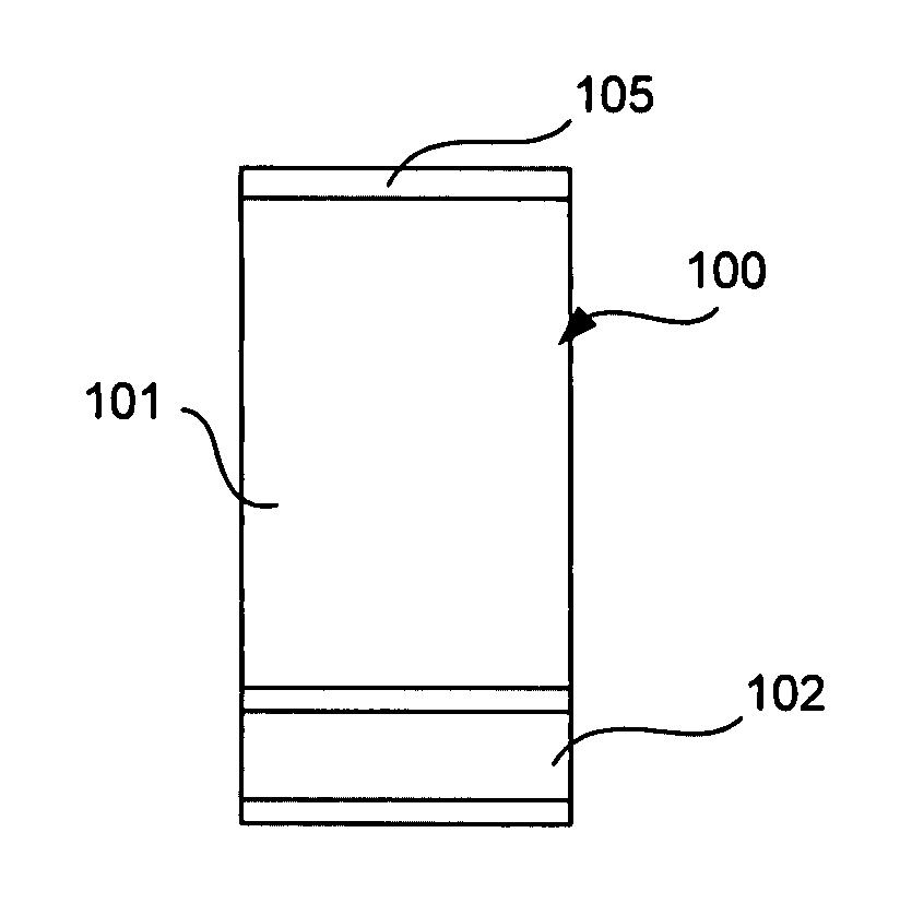
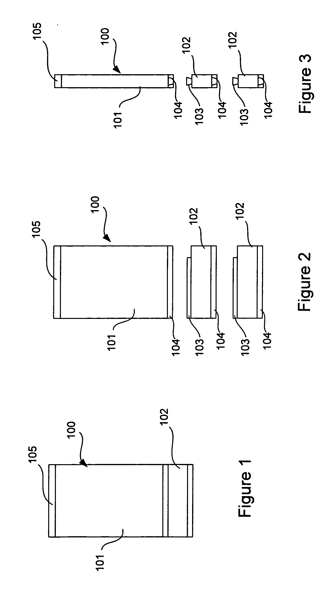
[0028]FIG. 7 shows a battery assembly 100 according to the present invention. The assembly has a generally planar cuboid cell 101 for supplying power to an electronic device such as a mobile phone. The cell 101 is suitable for supplying charge to an electronic device and can be rechargeable by known charging means, or can be a disposable pre-charged cell. Electrical contacts 407 are provided at one end of the cell so as to supply power from the cell 101 to an electronic device having corresponding electrical contacts. FIG. 1 shows a generally cuboid extender 102 attached to cell 101.
[0029]Smaller designs of electronic devices place a limit on the size of conventional cells that can be used to power the device. The cell 101 will have its maximum size determined by the smallest size of electronic device that it is required to power. By attaching the extender 102 to the cell, the size of the battery assembly 100 can be increased to fit a larger device.
[0030]FIG. 2 shows the battery ass...
third embodiment
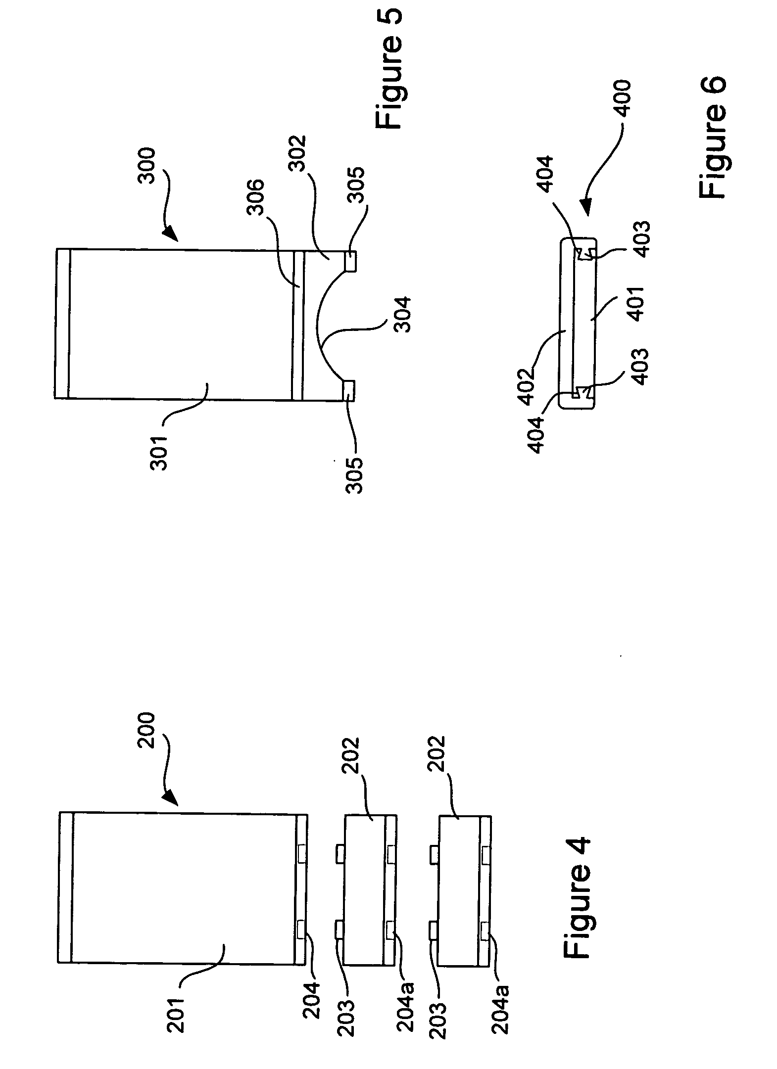
[0036]FIG. 5 shows a third embodiment with a battery assembly 300 having a cell 301 and an extender 302 attached to the cell 301. The extender 302 has two end pieces 305, a straight side 306 attached to the cell 301 and an arcuate side 304.
[0037]The straight side 306 of the extender 302 is removably attached to the cell 301 by either the sliding mechanism or the pin and aperture mechanism described in the previous two embodiments. The maximum length to which the cell 301 can be extended by the extender 302 is defined by the length of the “legs” formed where arcuate side 304 joins the side edges 305 This shape of extender 302 helps to make the battery assembly more lightweight than the generally cuboid shape of the previous embodiments, while still providing extension of the cell 301 to the required length.
[0038]In this embodiment, an arcuate recess is provided. However, it will be appreciated that any kind of recess can be used to minimize the size of the extension means 302. Furthe...
fourth embodiment
[0039]FIG. 6 shows an end view of a battery assembly 400 having a cell 401 and an extension means 402. The extension means 402 has mail fittings 403, which are operable to fit female fittings 404 provided in the cell 401.
[0040]The fittings 403 and 404 form a sliding mechanism so that the extension means 402 can be slidably engaged with the cell 401. The extender forms a sleeve around the cell 401 to extend the thickness of the cell and the width or length of the cell.
[0041]The extension means of this embodiment may be used in conjunction with that of the first, second and / or third embodiments so that all three dimensions of a cell may be increased or decreased as desired.
[0042]Although the extension means of the first, second and third embodiments have been shown as being attached to the cell at the opposite end of the cell from where the electrical contacts are provided, the may also be attached to the cell on one or both sides of the cell. This may be instead of, or in addition t...
PUM
 Abstract
Description
Claims
Application Information
 - R&D
- Intellectual Property
- Life Sciences
- Materials
- Tech Scout
- Unparalleled Data Quality
- Higher Quality Content
- 60% Fewer Hallucinations
Browse by: Latest US Patents, China's latest patents, Technical Efficacy Thesaurus, Application Domain, Technology Topic, Popular Technical Reports.
© 2025 PatSnap. All rights reserved.Legal|Privacy policy|Modern Slavery Act Transparency Statement|Sitemap|About US| Contact US: help@patsnap.com