
Aggregate signature schemes

a technology of aggregation and signature schemes, applied in the direction of ignition automatic control, instruments, electric controllers, etc., can solve the problems of prohibitively expensive, large active rfid tags, and large number of active rfid tags

Active Publication Date: 2008-03-20
MALIKIE INNOVATIONS LTD
View PDF23 Cites 105 Cited by
  • Summary
  • Abstract
  • Description
  • Claims
  • Application Information

AI Technical Summary

Benefits of technology

[0014] In another aspect, there is provided a method for verifying an aggregate digital signature comprising: obtaining the digital signature, the digital signature having a first signature component encrypting at least one other signature component using respective encryption keys, a first of which encrypts a first portion of data, and having at least one secondary signature component, each being generated from either the first signature component or a respective one of the at least one other signature component and a respective private key; generating a first decryption key using the first signature component and a second portion of data and decrypting the first signature component to obtain a recovered signature component; using the recovered signature component to recover additional signature components corresponding to the at least one other signature component by generating one or more subsequent decryption keys; recovering from the first of the at least one other signature components, a representation of the first portion of data; and examining the representation of the first portion of data for a predetermined characteristic to verify the digital signature.
[0015] In yet another aspect, there is provided a method for generating an aggregate digital signature at a plurality of signing stages comprising generating an initial pair of signature components; encrypting one of the initial pair of components in a next set of signature components, the next set of signature components including the other of the initial pair of components and two new signature components; and for subsequent signing stages, encrypting a previous signature component that in turn encrypts another previous signature component and generating an additional new signature component; wherein the number of signature components in the digital signature at each stage is one more than the total number of signing stages.

Problems solved by technology

The onboard power supply also requires more space and thus active RFID tags are generally larger and more expensive than passive RFID tags.
The above-noted implementation requires an RFID tag that is large enough to store a relatively large signature, e.g. 1024 bit digital Rivest-Shamir-Adleman (RSA) signature, which can be prohibitively expensive.
As a result, the authenticated RFID tags, when signed with an RSA signature, can only accommodate one signature without requiring a tag that may be too expensive to use.
The use of such relatively large RSA signatures also makes the use of multiple signatures on the same tag infeasible without increasing the tag size even further which can be even more prohibitively expensive.

Method used


Image

  • Aggregate signature schemes
  • Aggregate signature schemes
  • Aggregate signature schemes

Examples


Embodiment Construction

Authenticated RFID System and Example Supply Chain

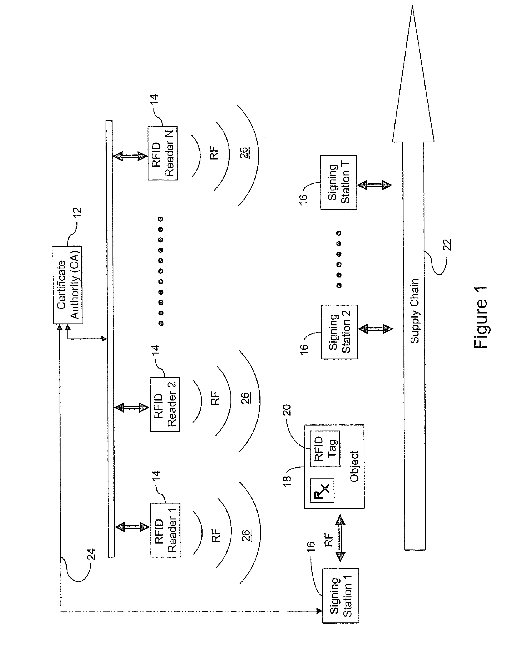
[0046] Referring to FIG. 1, an authenticated RFID system 10 is shown. The system 10 shown comprises a certificate authority (CA) 12 for issuing certificates to control the distribution of public keys in one embodiment, an arbitrary N number of RFID readers 14 distributed along a supply chain 22 for reading an RFID tag 20 affixed to an object 18 (e.g. a pharmaceutical product, consumer product, piece of luggage, mobile communication device, etc.), and an arbitrary T number of signing stations 16 for writing signatures to the RFID tags 20 in establishing an electronic pedigree for the tag 20. Each reader 14 produces a radio frequency (RF) field 26 which energizes the tags 20, which in this example are preferably passive. It will be appreciated that the tags 20 may also be active if the cost can be justified for the particular application.

[0047] The CA 12 preferably communicates with the readers 14 and the signing stations 16 over a ...


PUM


Abstract

An authenticated RFID system is provided that uses elliptic curve cryptography (ECC) to reduce the signature size and read / write times when compared to traditional public key implementations such as RSA. Either ECDSA or ECPVS can be used to reduce the signature size and ECPVS can be used to hide a portion of the RFID tag that contains sensitive product identifying information. As a result, smaller tags can be used or multiple signatures can be written at different stages in a manufacturing or supply chain. A key management system is used to distribute the verification keys and aggregate signature schemes are also provided for adding multiple signatures to the RFID tags, for example in a supply chain.

Description

[0001] This application claims priority from U.S. Application Nos. 60 / 824,921 filed on Sep. 8, 2006; 60 / 865,566 filed on Nov. 13, 2006; and 60 / 929,816 filed on Jul. 13, 2007; the contents of which are incorporated herein by reference.FIELD OF THE INVENTION [0002] The present invention relates generally to radio frequency identification (RFID) tags and RFID authentication systems, and has particular utility in signing and authenticating RFID tags. DESCRIPTION OF THE PRIOR ART [0003] Traditionally, objects such as inventory and commercial products have been given an associated identifier to allow the object to be tracked, identified and / or monitored. Recently, barcodes are becoming displaced by radio frequency identification (RFID) technology for providing the identifiers. RFID is beneficial as it provides an automatic identification system rather than requiring a user or machine to locate the barcode tag and then scan the barcode in a particular way. [0004] RFID relies on the storage...

Claims


Application Information

Patent Timeline
Patent Type & Authority Applications(United States)
IPC IPC(8): H04L9/14
CPCH04L9/3066H04L2209/805H04L9/3252
Inventor BROWN, DANIEL R.VANSTONE, SCOTT A.
Owner MALIKIE INNOVATIONS LTD
Learn More