
High thermal conductivity dielectric tape

a dielectric tape and high thermal conductivity technology, applied in the direction of insulating conductors, inorganic insulators, cables, etc., can solve the problems of reducing the efficiency and durability of components, the equipment as a whole, and the complications of discharging heat, and other difficulties of the prior ar

Active Publication Date: 2008-03-20
SIEMENS ENERGY INC
View PDF98 Cites 54 Cited by
  • Summary
  • Abstract
  • Description
  • Claims
  • Application Information

AI Technical Summary

Benefits of technology

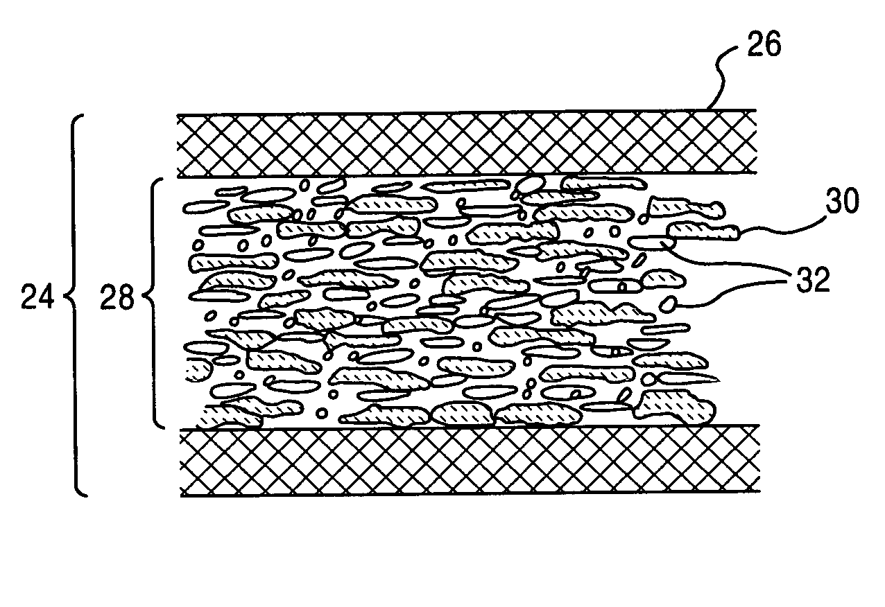
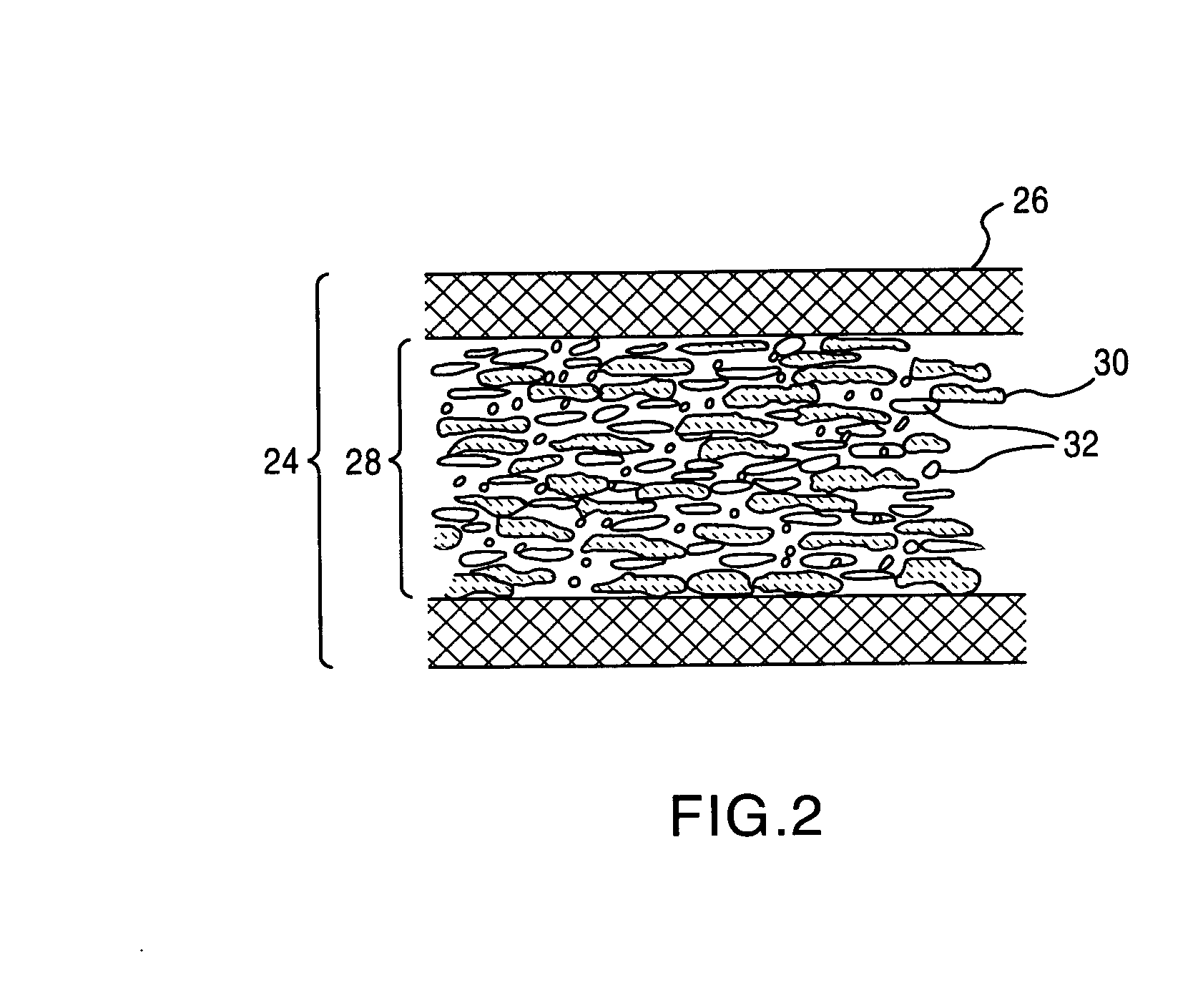
[0009]The filler layer will also have a binder resin that is uniformly mixed with the mica flakelets and filler particles. The amount of resin in the filler layer can vary, but should be kept to minimum at approximately 25-50% by volume of the filler layer. The glass carrier layers will also be impregnated with a thermoset polymeric resin, though it may be of a different type than that used in the filler layer, typically, the same types of polymeric resins are used for chemical compatibility of all the tape constituents, (i.e., epoxy resins). For ease of handling, the resins can be partially cured prior to application of the tape, and in some applications, a b-stage tape may be advantageous.

Problems solved by technology

Good electrical insulators, by their very nature, also tend to be good thermal insulators; a property which is undesirable.
Thermal insulating behavior, particularly for air-cooled electrical equipment and components, reduces the efficiency and durability of the components, as well as the equipment as a whole.
Unfortunately, this amount of insulation further adds to the complications of dissipating heat.
Other difficulties with the prior art exist, some of which will be apparent upon further reading.

Method used


Image

  • High thermal conductivity dielectric tape
  • High thermal conductivity dielectric tape
  • High thermal conductivity dielectric tape

Examples


Embodiment Construction

[0023]The present invention provides for a versatile insulating tape that comprises a highly thermally conductive dielectric layer sandwiched between two glass carrier layers. In the prior art, mica tapes are fragile and difficult to handle, they are thermally insulating, and not applicable to a wide range of industries. The present invention provides for an electrical insulation tape that uses the electrical resistivity properties of mica, the thermal conductivity of special thermally conductive, electrically insulative fillers in the dielectric layer, and the strength and flexibility of glass carriers.

[0024]The tape includes two glass carriers that sandwich a dielectric layer, with mica particles and thermally conductive, electrically insulative particles in a polymeric binder. The dielectric thermally conductive, electrically insulative filler layer is a combination of mica particles / flakelets and thermally conductive filler particles. The filler particles are highly thermally co...


PUM

PropertyMeasurementUnit
Lengthaaaaaaaaaa
Percent by volumeaaaaaaaaaa

Abstract

An electrical insulation tape that has a first and second carrier layer, and a dielectric thermally conductive, electrically insulative filler layer (24) that has mica particles / flakelets (6), filler particles (26) and a binder resin (28), disposed between the first and second carrier layers. The dielectric filler layer has mica flakelets (30), filler particles (32) and a binder resin. The ratio of mica flakelets to filler particles is at least 1:1 by volume, and the percentage of binder resin in the dielectric filler layer is 35-50% by volume. The first and second carrier layers are impregnated with a second resin.

Description

FIELD OF THE INVENTION[0001]The field of the invention relates to multi-purpose electrical insulation tapes.BACKGROUND[0002]With the use of any form of electrical equipment that includes high voltage or high current carrying conductors, there is typically a need for heat dissipation qualities of the insulating materials. With the push to continuously reduce the size and to streamline all electrical and electronic systems, there is a corresponding need to find better and more compact insulators and insulation systems.[0003]Various organic polymer thermoset resin materials, like epoxy, polyester, and phenolic formulations, have been used extensively in electrical insulation systems because of the practical benefits they possess; they are tough and flexible electrical insulation materials that can be easily adhered to surfaces. Traditional high voltage electrical insulation materials, such as mica particles in flake or splittings form and glass fiber, can be surface coated and bonded w...

Claims


Application Information

Patent Timeline
IPC IPC(8): H01B11/06
CPCH01B3/04B32B5/26
Inventor MILLER, MARK L.
Owner SIEMENS ENERGY INC
Learn More