
Apparatus, system, and method for calibrating a holographic storage device

a technology of holographic storage and apparatus, applied in the field of holographic storage device calibration, can solve the problems of limiting future increases in areal densities, affecting the interoperability of the device, and the wavelength of available lasers

Inactive Publication Date: 2008-03-13
IBM CORP
View PDF8 Cites 19 Cited by
  • Summary
  • Abstract
  • Description
  • Claims
  • Application Information

AI Technical Summary

Benefits of technology

[0024]Furthermore, the described features, advantages, and characteristics of the invention may be combined in any suitable manner in one or more embodiments. One skilled in the relevant art will recognize that the invention may be practiced without one or more of the specific features or advantages of a particular embodiment. In other instances, additional features and advantages may be recognized in certain embodiments that may not be present in all embodiments of the invention.
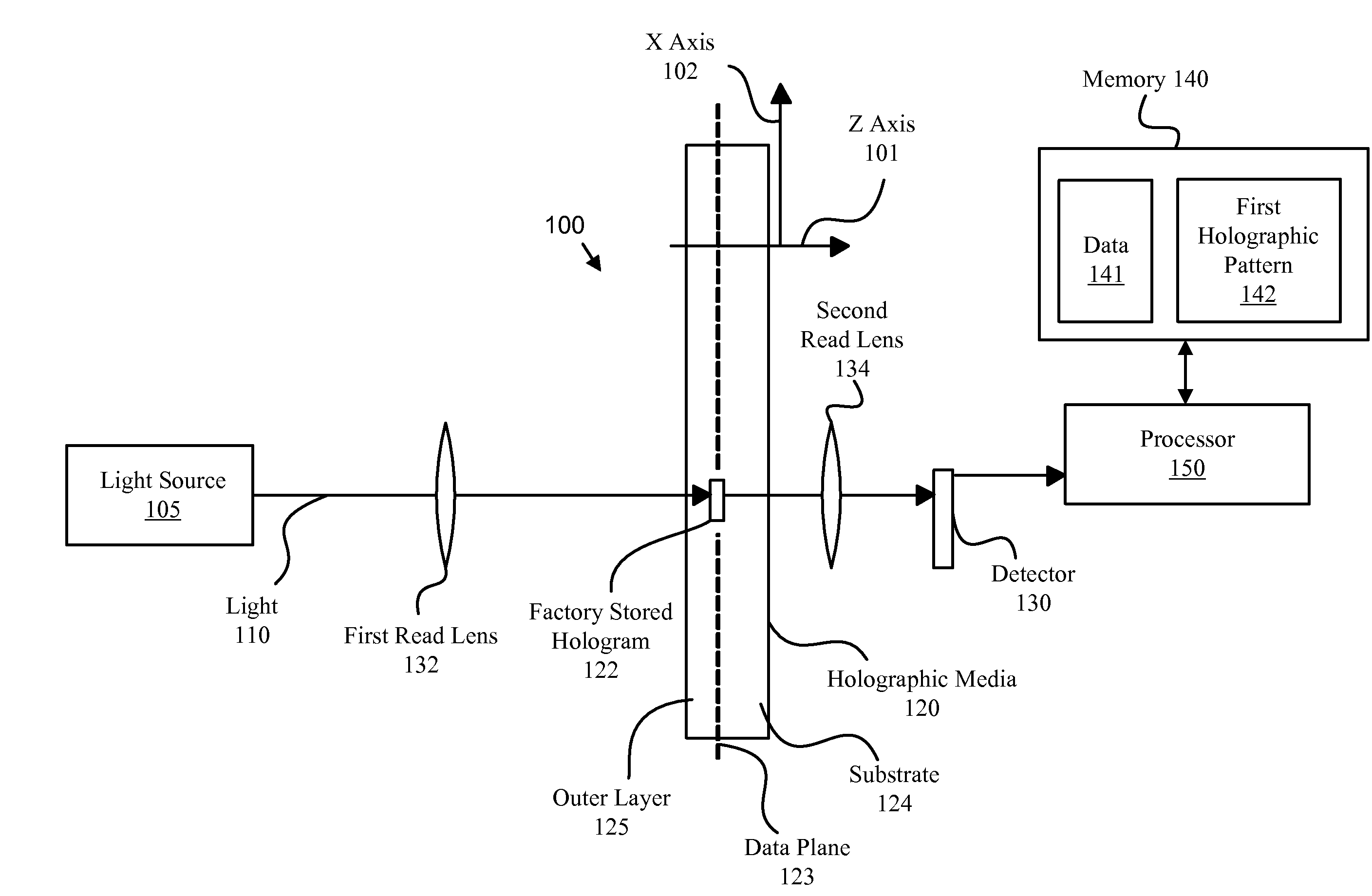
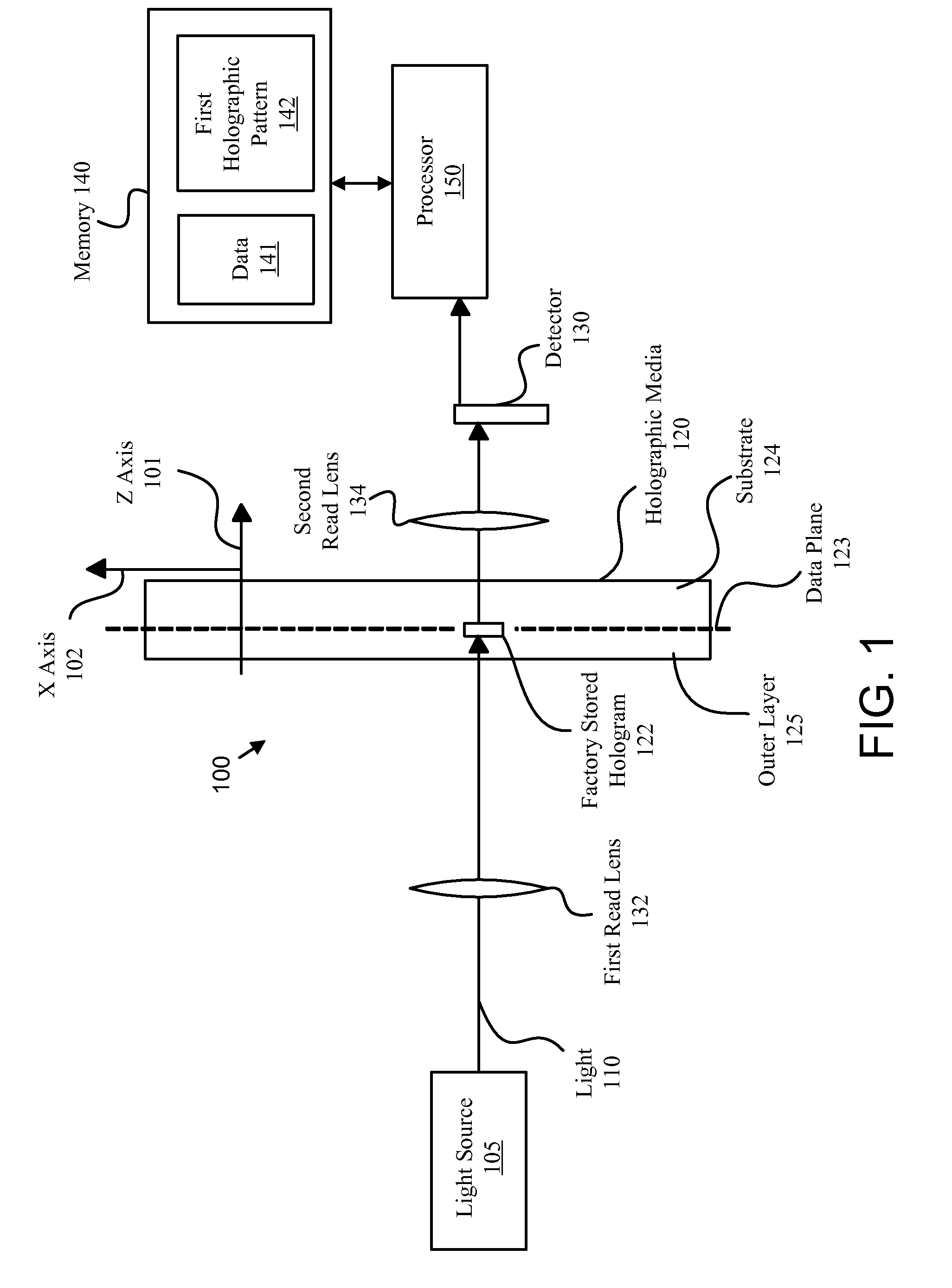
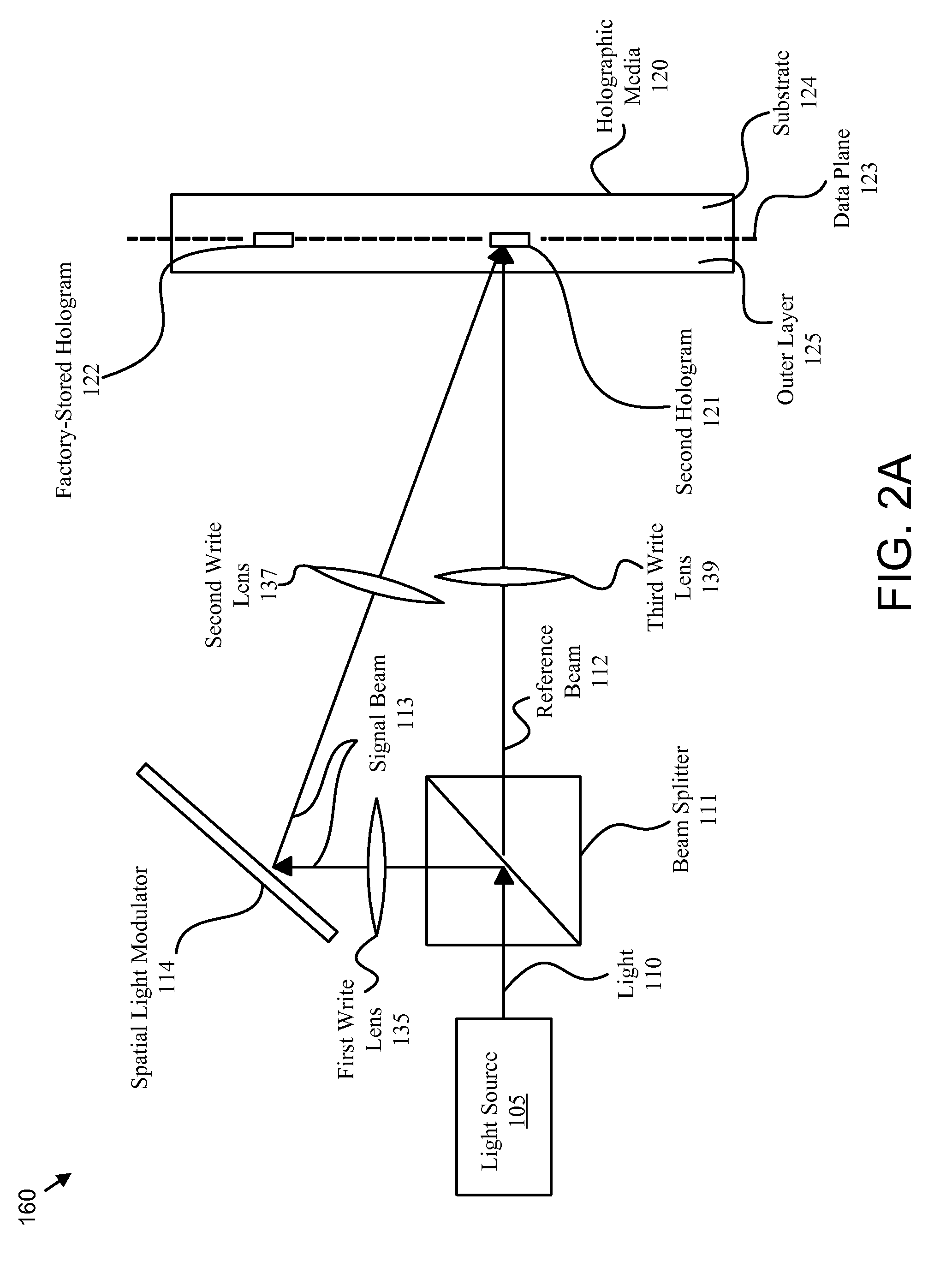
[0025]The embodiment of the present invention calculates a read difference using a factory-stored hologram. In addition, the present invention may calibrate the read channel with the read difference. The present invention may also calculate a write difference and calibrate a write channel with the write difference. These features and advantages of the present invention will become more fully apparent from the following description and appended claims, or may be learned by the practice of the invention as set forth hereinafter.

Problems solved by technology

Unfortunately, limitations such as material limitations, paramagnetic limits, limitations on the wavelengths of available lasers, and the like may restrict future increases in areal densities.
Unfortunately, a holographic storage device may be sufficiently sensitive to differences between data written by the holographic storage device and data written by other holographic storage devices that interoperability is compromised.
For example, a first and second holographic storage device produced by different manufacturers may each be unable to read data written by the other because of read and write channel sensitivities.

Method used


Image

  • Apparatus, system, and method for calibrating a holographic storage device
  • Apparatus, system, and method for calibrating a holographic storage device
  • Apparatus, system, and method for calibrating a holographic storage device

Examples


Embodiment Construction

[0037]Many of the functional units described in this specification have been labeled as modules, in order to more particularly emphasize their implementation independence. For example, a module may be implemented as a hardware circuit comprising custom VLSI circuits or gate arrays, off-the-shelf semiconductors such as logic chips, transistors, or other discrete components. A module may also be implemented in programmable hardware devices such as field programmable gate arrays, programmable array logic, programmable logic devices or the like.

[0038]Modules may also be implemented in software for execution by various types of processors. An identified module of executable code may, for instance, comprise one or more physical or logical blocks of computer instructions, which may, for instance, be organized as an object, procedure, or function. Nevertheless, the executables of an identified module need not be physically located together, but may comprise disparate instructions stored in ...


PUM


Abstract

An apparatus, system, and method are disclosed for calibrating a holographic storage device. A read channel reads a factory-stored hologram from a holographic media. A calculation module calculates a read difference between the read factory-stored hologram and a first holographic pattern that digitally describes the factory-stored hologram. In one embodiment, a calibration module calibrates the read channel with the read difference.

Description

BACKGROUND OF THE INVENTION[0001]1. Field of the Invention[0002]This invention relates to holographic storage devices and more particularly relates to calibrating holographic storage devices.[0003]2. Description of the Related Art[0004]Data processing systems are storing ever-larger quantities of data. To meet this increasing demand, storage device manufacturers are increasing the areal densities of magnetic storage devices, optical storage devices, and the like. Unfortunately, limitations such as material limitations, paramagnetic limits, limitations on the wavelengths of available lasers, and the like may restrict future increases in areal densities.[0005]Holographic storage may support increased data storage densities, providing a technology to support the increasing demand for storage. However, to be a viable storage technology, holographic storage media must be interchangeable among a plurality of holographic storage devices, including different models of holographic storage de...

Claims


Application Information

Patent Timeline
IPC IPC(8): G11C7/00G11B7/00
CPCG11B7/0065G11C13/042G11B7/00781
Inventor BATES, ALLEN KEITHWINARSKI, DANIEL JAMES
Owner IBM CORP
Learn More