Sampled data averaging circuit
a technology of sampling circuit and data, applied in the field of sampling data averaging circuit, can solve the problem of inability to sample input data by an optimal number of sampling times
- Summary
- Abstract
- Description
- Claims
- Application Information
AI Technical Summary
Benefits of technology
Problems solved by technology
Method used
Image

Examples
first embodiment
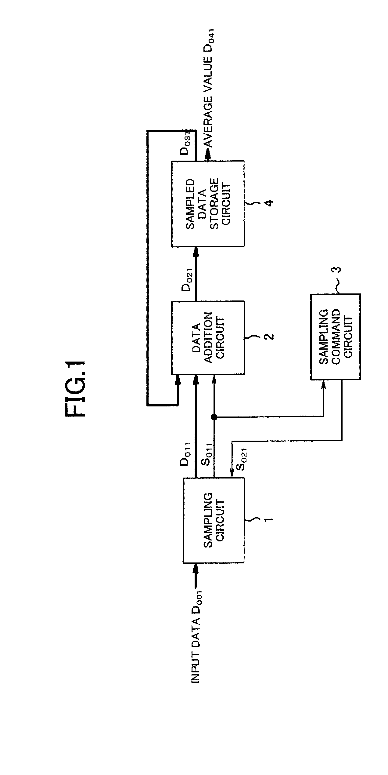
[0049]FIG. 10 shows a sampled data averaging circuit of the invention. The averaging circuit comprises a data storage selector 5 and a sampling times setting circuit 6 in addition to a sampling circuit 1, a data addition circuit 2, a sampling command circuit 3a and a sampled data storage circuit 4.
[0050]As shown in FIG. 11, the data storage selector 5 comprises selector circuits 51[0] to 51[N+M−1], and receives output data D011, with a bit width of N bits from the sampling circuit 1 and sampling times data D061 output from the sampling times setting circuit 6, and generates output data D051, which is supplied to the data addition circuit 2. The output data D051 has D051[0] to D051[N+M-1].
[0051]FIG. 12 shows a configuration of the data storage selector 5 when N=3 and M=3. That is, selector circuits 51[0] to 51[5] are provided, and data D051 (D051[0] to D051[5]) with a bit width of 6 bits, is output.
[0052]Of the selector circuits 51[0] to 51[5] in FIG. 12, the selector circuit 51[3] i...
second embodiment
[0071]FIG. 18 shows a sampled data averaging circuit of the invention. This averaging circuit comprises a sampling circuit 1, a data addition circuit 2, a sampling command circuit 3a, a sampled data storage circuit 4a, a data storage selector 5, and a sampling times setting circuit 6.
[0072]As shown in FIG. 19, the sampled data storage circuit 4a comprises storage circuits 42[0] to 42[N+M−1], which are flip-flops, and to which a clock pulse and a reset pulse are supplied. Output data D021 (D021[0] to D021[N+M-1]) of the data addition circuit 2 is also supplied to the storage circuits 42[0] to 42[N+M−1]. The storage circuits 42[0] to 42[N+M−1] capture and store data D021[0] to D021[N+M-1] in sync with the clock pulse, for output as D032[0] to D032[N+M-1]. D032 [0] to D032[N+M−1] are data D032, and D031[M] to D031[N+M-1] are output data D042 of the sampled data averaging circuit.
[0073]As a result of supply of the reset pulse, the initial value of the storage circuit 42[M−1] each time a...
third embodiment
[0079]FIG. 21 shows a sampled data averaging circuit of the invention. This averaging circuit comprises a sampling circuit 1, a data addition circuit 2a, a sampling command circuit 3a, a sampled data storage circuit 4a, a data storage selector 5, a sampling times setting circuit 6a, a maximum value detection circuit 7, and a minimum value detection circuit 8.
[0080]As shown in FIG. 22, the data addition circuit 2a comprises, in addition to an adder 21 and a selector 22, a counter 23, a comparator 24, and a computing unit 25. The portion including the adder 21 and selector 22 is the same as the data addition circuit 2 shown in FIG. 3. Output data D122 of the selector 22 is supplied to the computing unit 25. The counter 23 performs counting-up each time a sampling-completed flag S011 changes from 0 to 1. The count value D123 of the counter 23 is supplied to the comparator 24. When the count value D123 of the counter 23 becomes equal to sampling times data D062=2I+2 supplied from the sa...
PUM
 Abstract
Description
Claims
Application Information
 - R&D
- Intellectual Property
- Life Sciences
- Materials
- Tech Scout
- Unparalleled Data Quality
- Higher Quality Content
- 60% Fewer Hallucinations
Browse by: Latest US Patents, China's latest patents, Technical Efficacy Thesaurus, Application Domain, Technology Topic, Popular Technical Reports.
© 2025 PatSnap. All rights reserved.Legal|Privacy policy|Modern Slavery Act Transparency Statement|Sitemap|About US| Contact US: help@patsnap.com