Head slider
a slider and head technology, applied in the field of head sliders, can solve the problems of electromagnetic transducer protrusion, electromagnetic transducer cannot be allowed to write magnetic bit data of a high density, etc., and achieve the effect of reducing flying heigh
- Summary
- Abstract
- Description
- Claims
- Application Information
AI Technical Summary
Benefits of technology
Problems solved by technology
Method used
Image

Examples
first embodiment
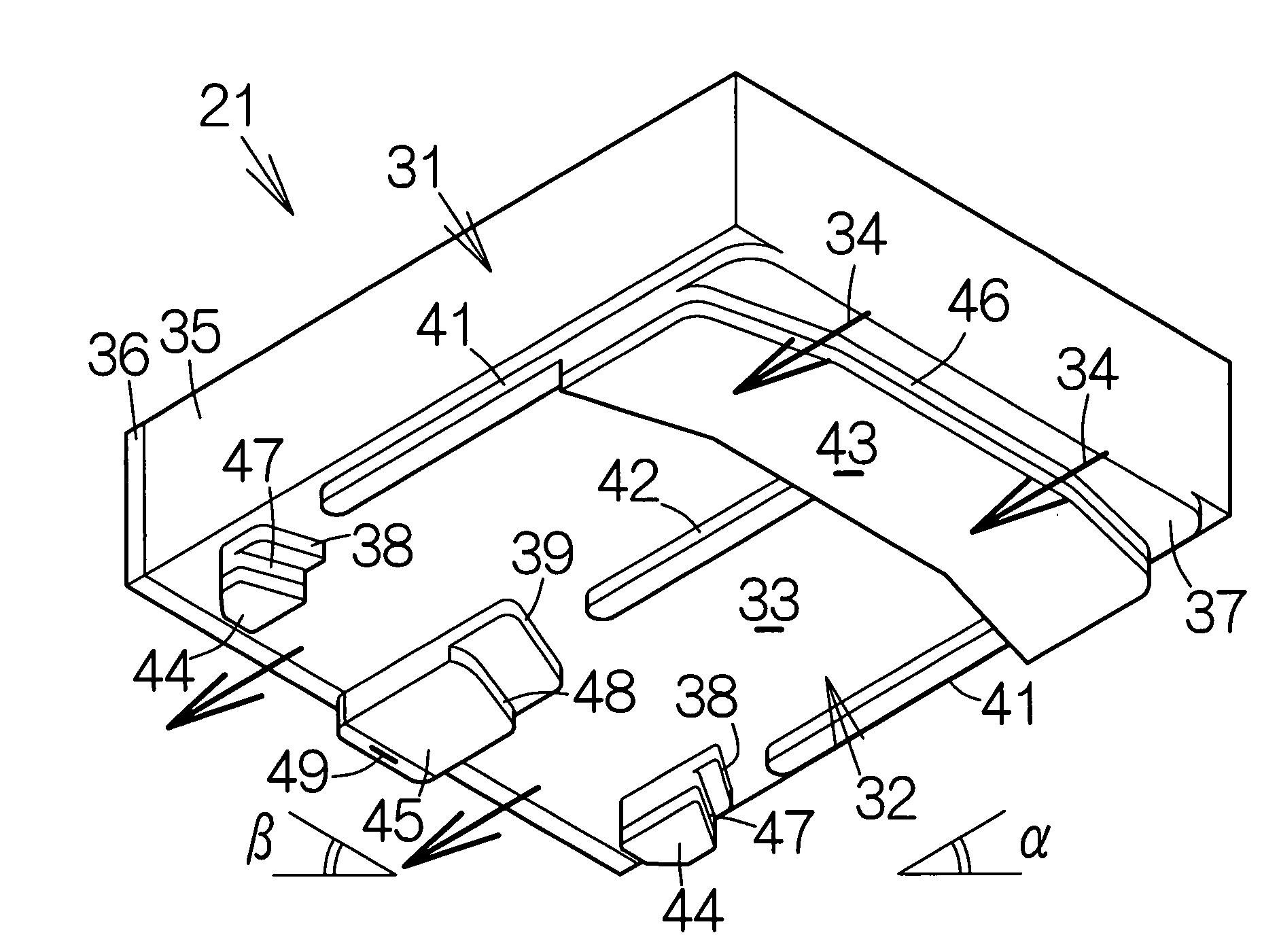
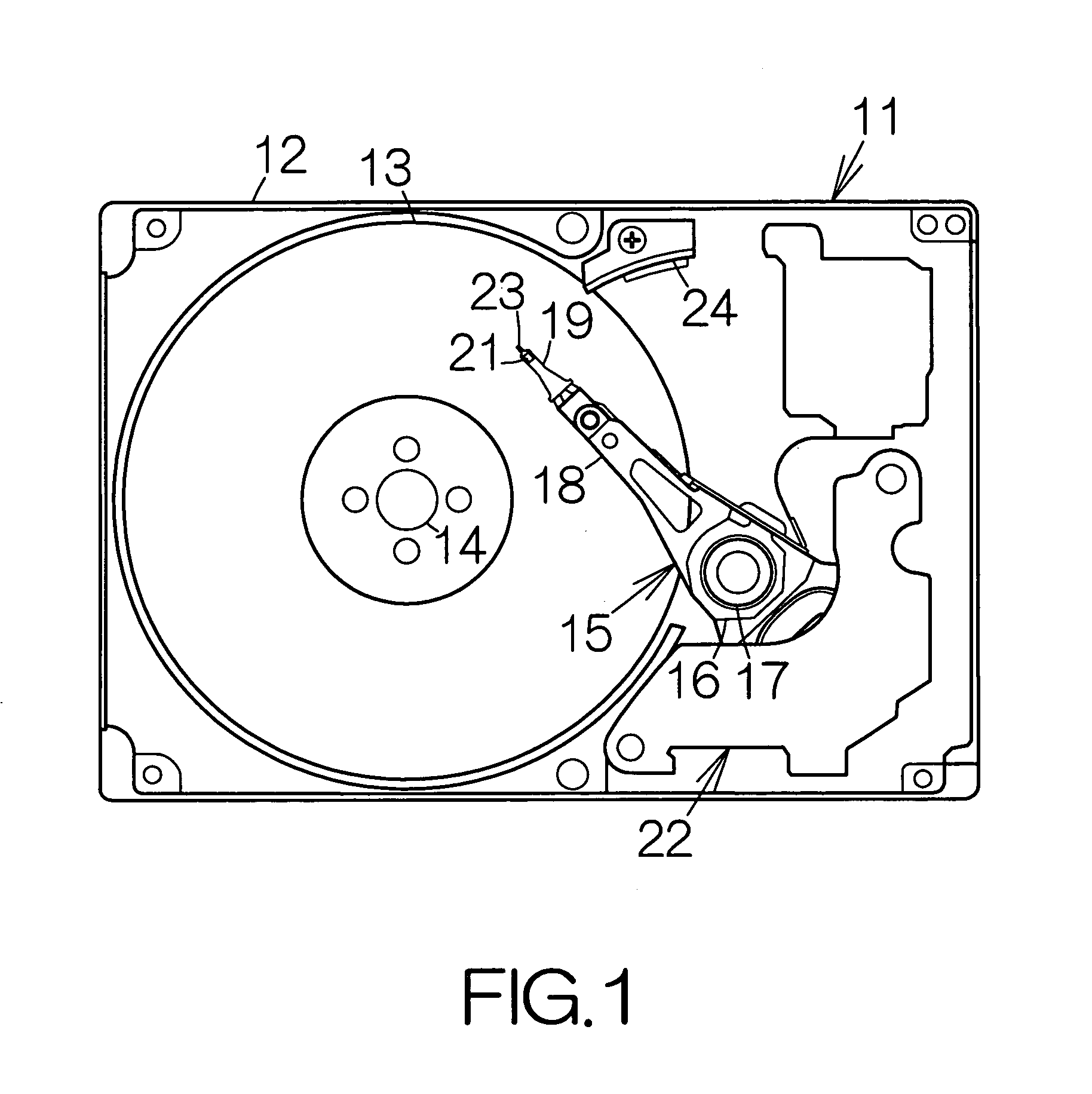
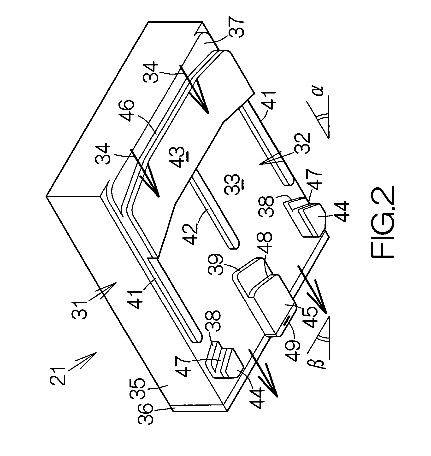
[0069]FIG. 2 illustrates the flying head slider 21 according to the present invention. The flying head slider 21 includes a slider body 31 in the form of a flat parallelepiped. A medium-opposed surface or bottom surface 32 is defined over the slider body 31 so as to face the magnetic recording disk 13 at a distance. A flat reference surface or base surface 33 is defined on the bottom surface 32. When the magnetic recording disk 13 rotates, airflow 34 acts on the bottom surface 32 in the direction from the inflow or leading end toward the outflow or trailing end of the slider body 31. The slider body 31 may comprise a base 35 made of Al2O3—TiC and a head protection film 36 made of Al2O3 (alumina), for example. The head protection film 36 is overlaid on the outflow or trailing end of the base 35.
[0070]A front rail 37 stands upright from the base surface 33 of the bottom surface 32 near the inflow end of the slider body 31. The front rail 37 is designed to extend along the inflow end o...
second embodiment
[0086]FIG. 9 illustrates a flying head slider 21a according to the present invention. The flying head slider 21a may be incorporated in the hard disk drive 11 in place of the aforementioned flying head slider 21. As mentioned in FIG. 9, the front air bearing surface 43 is set at the highest position from the base surface 33 in the flying head slider 21a. As shown in FIG. 10, the auxiliary rear air bearing surfaces 44, 44 are set at a third height H3 smaller than the first height H1 from the base surface 33. The rear air bearing surface 45 may be set at the aforementioned second height H2. The third height H3 is set larger than the second height H2. Like reference numerals are attached to the structure or components equivalent to those of the aforementioned flying head slider 21.
[0087]The rear air bearing surface 45 is distanced from the surface of the magnetic recording disk 13 by an amount larger than the distance between the front and auxiliary rear air bearing surfaces 43, 44 and...
third embodiment
[0094]FIG. 13 schematically illustrates a flying head slider 21b according to the present invention. The front, auxiliary rear and rear air bearing surfaces 43, 44, 44, 45 are set at the highest position from the base surface 33 in the flying head slider 21b. As shown in FIG. 14, the front and rear air bearing surfaces 43, 45 are set at the first height H1 from the base surface 33. The electromagnetic transducer 49 is embedded in the rear center rail 39 at the second height H2 lower than the first height H1 from the base surface 33 at a position distanced from the rear air bearing surface 45.
[0095]The rear center rail 39 includes the aforementioned rear pedestal 53 and first and second protection films 71, 72 formed on the rear pedestal 53. The first protection film 71 has the first thickness. The second protection film 72 has the second thickness smaller than the first thickness. The surface of the first protection film 71 serves to provide the rear air bearing surface 45. The seco...
PUM
| Property | Measurement | Unit |
|---|---|---|
| height | aaaaa | aaaaa |
| thickness | aaaaa | aaaaa |
| magnetic flux | aaaaa | aaaaa |
Abstract
Description
Claims
Application Information
 - R&D
- Intellectual Property
- Life Sciences
- Materials
- Tech Scout
- Unparalleled Data Quality
- Higher Quality Content
- 60% Fewer Hallucinations
Browse by: Latest US Patents, China's latest patents, Technical Efficacy Thesaurus, Application Domain, Technology Topic, Popular Technical Reports.
© 2025 PatSnap. All rights reserved.Legal|Privacy policy|Modern Slavery Act Transparency Statement|Sitemap|About US| Contact US: help@patsnap.com