
Electromagnetic Pump

a technology of electromagnetism and pumps, applied in the direction of machines/engines, liquid fuel engines, positive displacement liquid engines, etc., can solve the problems of difficult service and maintenance of pump installations, and achieve the effect of maximizing the magnitude of magnetic forces

Inactive Publication Date: 2008-02-28
INDUCTOTHERM INDS
View PDF51 Cites 7 Cited by
  • Summary
  • Abstract
  • Description
  • Claims
  • Application Information

AI Technical Summary

Benefits of technology

This design enables efficient and maintainable pumping of electrically conductive materials by maximizing magnetic forces and allowing for easy assembly and disassembly, improving flow control and preventing material freezing during non-use through electromagnetic jogging.

Problems solved by technology

These pump installations are difficult to service and maintain.

Method used


Image

  • Electromagnetic Pump
  • Electromagnetic Pump
  • Electromagnetic Pump

Examples


Embodiment Construction

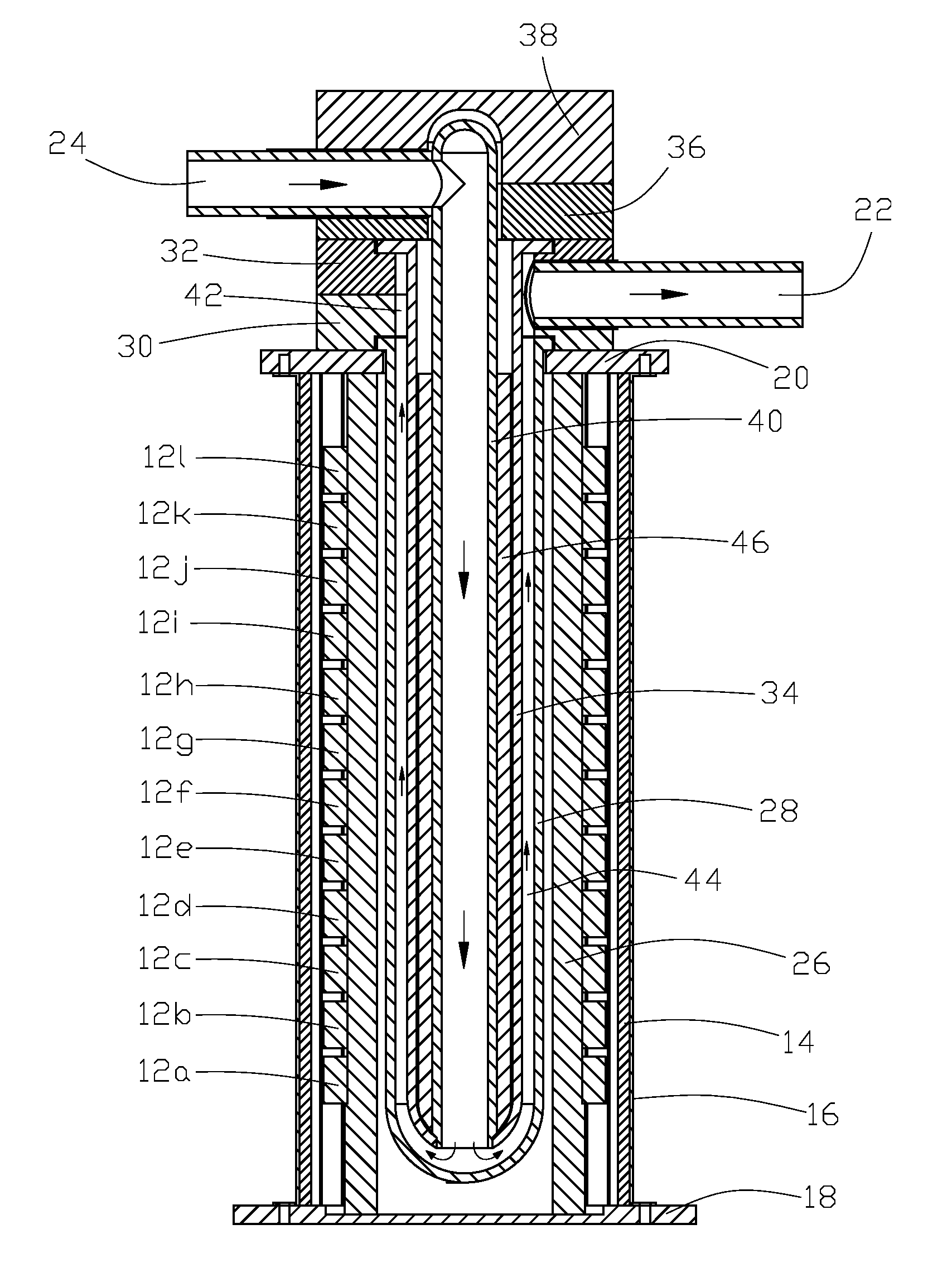
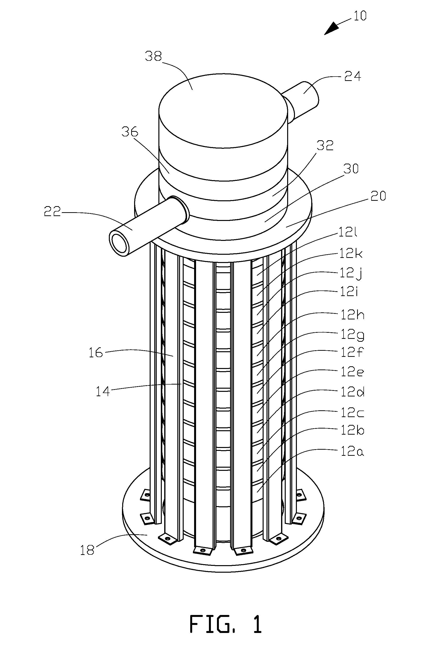
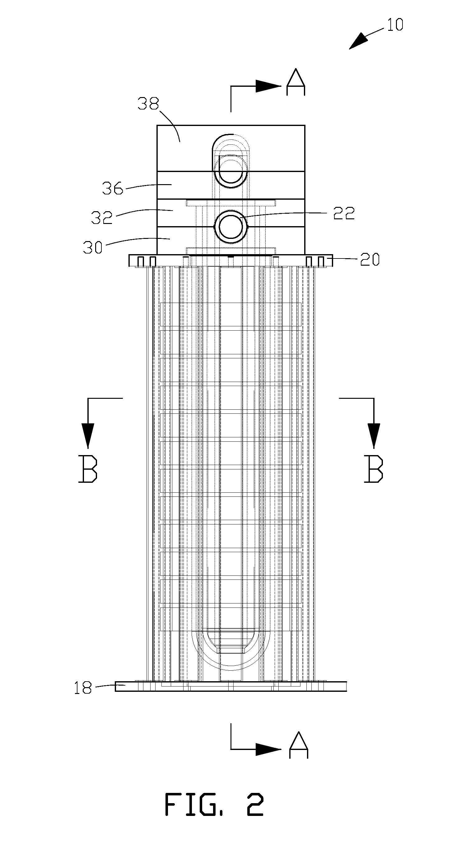
[0016] Referring now to the drawings, wherein like numerals indicate like elements, there is shown in the figures one example of electromagnetic pump 10 of the present invention for pumping an electrically conductive material, such as an electrically conductive molten metal. In FIG. 1, twelve induction coils (12a through 12l) as further described below, are surrounded by a plurality of vertical magnetic shunts 14 held in place by shunt supports 16, which are attached to base 18 at one end, and to yoke 20 at the opposing end. The base and yoke may optionally be formed from a magnetic material to provide bottom and top magnetic field containment. Other shunt and outer support arrangements as known in the art may be used in lieu of the shunt and support arrangements shown in FIG. 1. Pump inlet 24 and pump outlet 22 in this non-limiting example of the invention, are cylindrically formed from a suitable heat-resistant material.

[0017] Referring now to FIG. 3(a), which is a side sectional...


PUM


Abstract

An electromagnetic pump has a supply section and a magnetic force pumping section wherein flow of an electrically conductive material through the supply section is opposite to the flow of the material in the magnetic force pumping section in some examples. Multiple coils surround the supply and magnetic force pumping sections. Current flowing through the multiple coils creates magnetic fields that magnetically couple with a magnetic material disposed between the supply and magnetic force pumping sections so that the fields penetrate the electrically conductive material in the magnetic force pumping section substantially perpendicular to the desired flow direction which maximizes the magnitudes of magnetic forces applied to the electrically conductive material. Alternatively the electromagnetic pump has a supply section and a magnetic force pumping section wherein flow of an electrically conductive material through the supply section is in the same direction as the flow of the material in the magnetic force pumping section.

Description

CROSS REFERENCE TO RELATED APPLICATIONS [0001] This is a divisional application of application Ser. No. 10 / 825,634, filed Apr. 15, 2004, which application claims the benefit of U.S. Provisional Application No. 60 / 464,317, filed Apr. 21, 2003, both of which applications are hereby incorporated herein by reference in their entireties.FIELD OF THE INVENTION [0002] The present invention relates to electromagnetic pumps that move an electrically conductive fluid by interaction with magnetic fields. BACKGROUND OF THE INVENTION [0003] Electromagnetic pumps can be used to pump electrically conductive fluids, such as an electrically conductive molten metal composition. An advantage of an electromagnetic pump is that the fluid can be magnetically induced to move through a tube or conduit without the use of mechanical pump components inside of the conduit. [0004] Known electromagnetic pumps are either submersed in, or integrally attached to, the source of the electrically conductive fluid, suc...

Claims


Application Information

Patent Timeline
Patent Type & Authority Applications(United States)
IPC IPC(8): F04B15/00F04B17/00F04B15/04F04B17/04
CPCF04B15/04F04B17/04F04B17/00F04B53/16F05B2210/11F05B2260/60Y10S417/00
Inventor PEYSAKHOVICH, VITALY A.FISHMAN, OLEG S.TABATABAEI, EMAD
Owner INDUCTOTHERM INDS
Learn More