
Electrochromic Devices With Thin Bezel-Covered Edge

a technology of optically transparent devices and edges, applied in the direction of mirrors, instruments, mountings, etc., to achieve the effect of maintaining uniform coloration of ec mirrors and minimizing the contribution of transparent conductors to hu

Inactive Publication Date: 2008-02-28
GENTEX CORP
View PDF34 Cites 30 Cited by
  • Summary
  • Abstract
  • Description
  • Claims
  • Application Information

AI Technical Summary

Benefits of technology

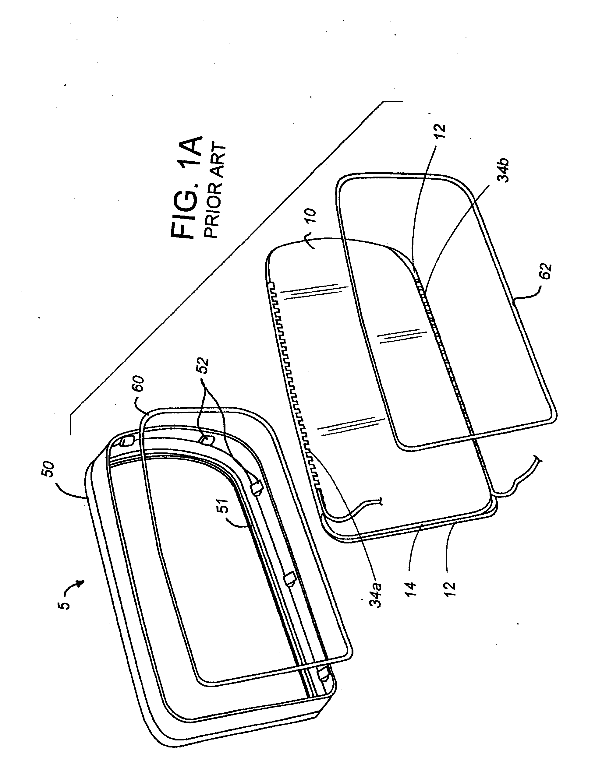
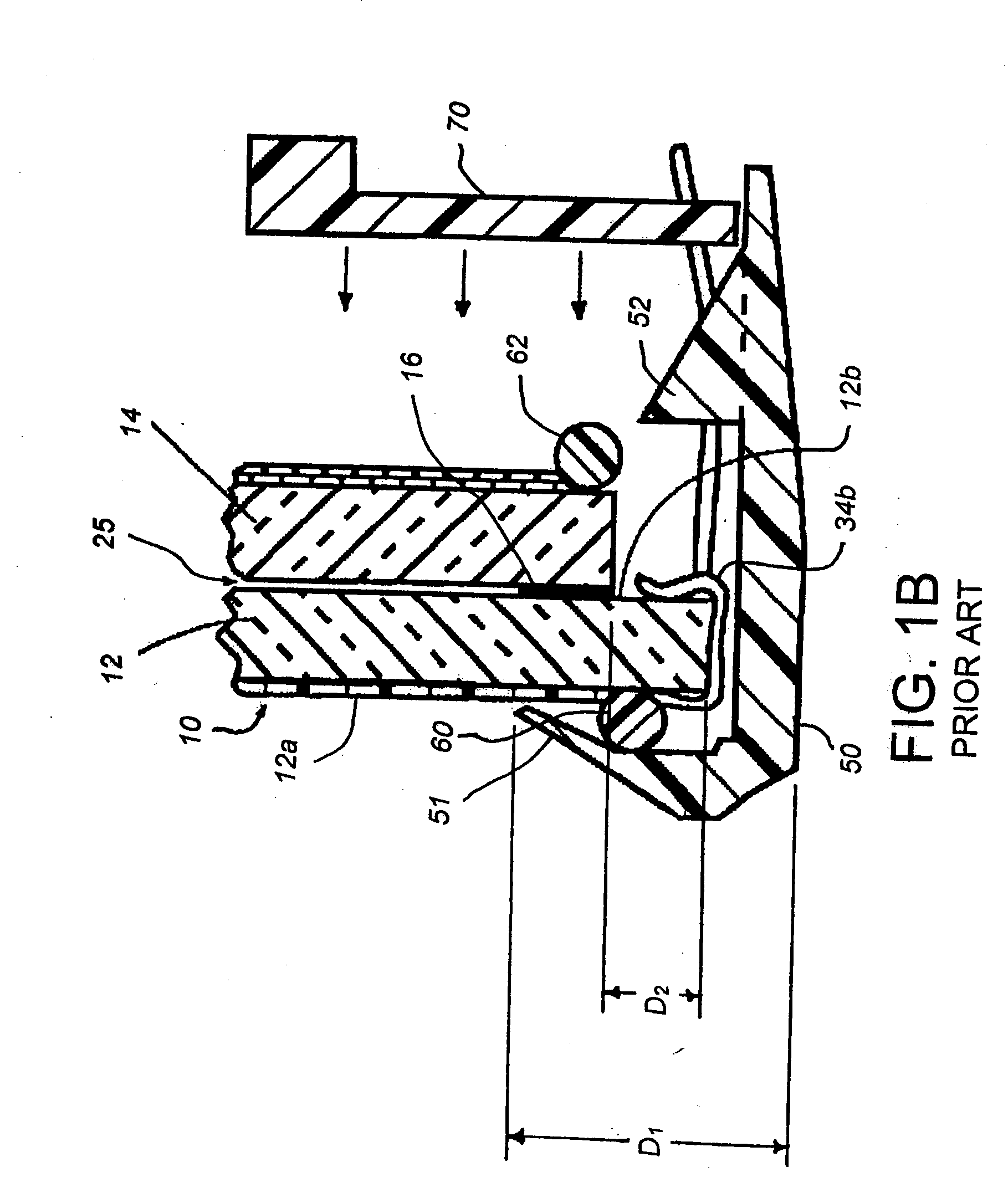
[0009] In another aspect of the present invention, a rearview mirror assembly for a vehicle includes a mirror housing defining an interior and a front opening and having a positioning device mounted therein. A mirror element and a carrier supporting the mirror element are positioned in the front opening and are operably attached to the positioning device for angular adjustment. A bezel is disposed around a periphery of the mirror element. The bezel has a laterally extending fin that slidingly engages an inside surface of the mirror housing for closing the interior to prevent visibility into the interior of the mirror housing.
[0013] In yet further embodiments, a substantially transparent seal material is used. In at least one related embodiment, the substantially transparent seal material is capable of withstanding without losing adhesive strength ultra-violet and, or, infrared light rays being directly impinged thereon.

Problems solved by technology

While the above-described structure is readily manufacturable, styling concerns have arisen with respect to the width of the front lip of the bezel of an electrochromic mirror subassembly.

Method used


Image

  • Electrochromic Devices With Thin Bezel-Covered Edge
  • Electrochromic Devices With Thin Bezel-Covered Edge
  • Electrochromic Devices With Thin Bezel-Covered Edge

Examples


Embodiment Construction

[0075] Reference will now be made in detail to the present preferred embodiments of the invention, examples of which are illustrated in the accompanying drawings. Wherever possible, the same reference numerals will be used throughout the drawings to refer to the same or like parts. In the drawings, the depicted structural elements are not to scale and certain components are enlarged relative to the other components for purposes of emphasis and understanding.

[0076] As described above, the electro-optic mirror subassemblies provide the advantage of a reduced bezel front lip width of preferably about 4 mm or less, and more preferably less than about 3.6 mm, while still extending over all of the seal width, and preferably extending about 0.5 mm beyond an innermost edge of the seal so as to sufficiently obscure the view of the seal. According to some aspects of the present invention, a bezel may not even be utilized due to other inventive techniques for obscuring the view of the seal th...


PUM

PropertyMeasurementUnit
thicknessaaaaaaaaaa
reflectivityaaaaaaaaaa
width D1aaaaaaaaaa

Abstract

A mirror includes an electro-optic mirror subassembly, and a thin-profiled bezel attached around a perimeter of the electrochromic mirror subassembly. The electro-optic mirror subassembly is supported on a carrier by an adheringly bonded heater and foam tape in a laminar arrangement. The bezel may be bonded to an edge of the front surface of the front element of the electro-optic mirror subassembly, and / or may be bonded and / or interlockingly mechanically attached to an edge of the carrier. Alternatively, the bezel can be a strip of paint or thin coating material. The bezel can be molded in place, or can be pre-molded and elastically stretched to permit assembly. In one form, the bezel includes a laterally-extending fin that prevents seeing past the bezel into the inside of a mirror housing. In at least one embodiment, the assembly has no bezel or only a bezel on one edge.

Description

CROSS-REFERENCE TO RELATED APPLICATION [0001] This is a divisional of U.S. patent application Ser. No. 10 / 430,885, filed May 6, 2003, entitled ELECTROCHROMIC DEVICES WITH THIN BEZEL-COVERED EDGE which is a continuation-in-part of U.S. patent application Ser. No. 10 / 260,741, filed Sep. 30, 2002, entitled ELECTROCHROMIC DEVICES HAVING NO POSITIONAL OFFSET BETWEEN SUBSTRATES, and U.S. patent application Ser. No. 09 / 884,717, filed Jun. 19, 2001, entitled COUPLED ELECTROCHROMIC COMPOUNDS WITH PHOTOSTABLE DICATION OXIDATION STATES, now U.S. Pat. No. 6,560,004, which is a continuation of U.S. patent application Ser. No. 09 / 350,879, filed on Jul. 9, 1999, which is now U.S. Pat. No. 6,249,369, the entire contents of which are incorporated herein by reference.BACKGROUND OF THE INVENTION [0002] The present invention generally relates to electro-optic devices and apparatus incorporating these devices. More particularly, the invention relates to electro-optic devices used in architectural window...

Claims


Application Information

Patent Timeline
Patent Type & Authority Applications(United States)
IPC IPC(8): G02F1/153G02B5/08G02B7/182C09K9/02G02F1/1503
CPCC09K9/02G02F1/1521G02F2001/1512G02F2001/1502G02F1/153G02F1/1503G02F2001/15145
Inventor TONAR, WILLIAM L.BAUER, FREDERICK T.ARNOLD, JOHN W.CAMMENGA, DAVID J.CARTER, JOHN W.BUSSCHER, BRADLEY L.FOGG, JEREMY A.
Owner GENTEX CORP
Learn More