
Image Display Method, Image Display Device, Image Display Monitor, and Television Receiver

a technology of image display and image, applied in the direction of static indicating devices, instruments, television systems, etc., can solve the problems of moving image blur and unresolved problems, and achieve the effect of suppressing moving image blur, preventing flicker, and high-quality moving imag

Inactive Publication Date: 2009-07-02
SHARP KK
View PDF45 Cites 12 Cited by
  • Summary
  • Abstract
  • Description
  • Claims
  • Application Information

AI Technical Summary

Benefits of technology

The present invention provides an image display method and device that solves the problem of flicker visibility and moving image blur by displaying images by dividing one frame period into multiple subframe periods and controlling the luminance of each subframe period. The frequency of the one frame period falls in the range of 50 to 70 Hz. The method includes a time-division driving that controls the subframe periods so that the luminance of the first subframe period is greater than the frame average luminance, and the luminance of the second subframe period is smaller than the frame average luminance. The contrast ratio between the first and second subframe periods is set to not greater than 1.5 when the frame average luminance is 150 CD / m2, and to not greater than 2.3 when the frame average luminance is 200 CD / m2. This results in a high-quality moving image display with reduced flicker and noise.

Problems solved by technology

In a normal display made by such a hold-type display device, there arises a problem with moving image blur when a moving image is displayed.
Such a problem arises from the fact that a pixel retains a display content even in its non-selection period according to a hold-type display device.
This problem will not be solved even if a response speed of the pixel is improved.
This, however, causes the following problem.

Method used


Image

  • Image Display Method, Image Display Device, Image Display Monitor, and Television Receiver
  • Image Display Method, Image Display Device, Image Display Monitor, and Television Receiver
  • Image Display Method, Image Display Device, Image Display Monitor, and Television Receiver

Examples


Embodiment Construction

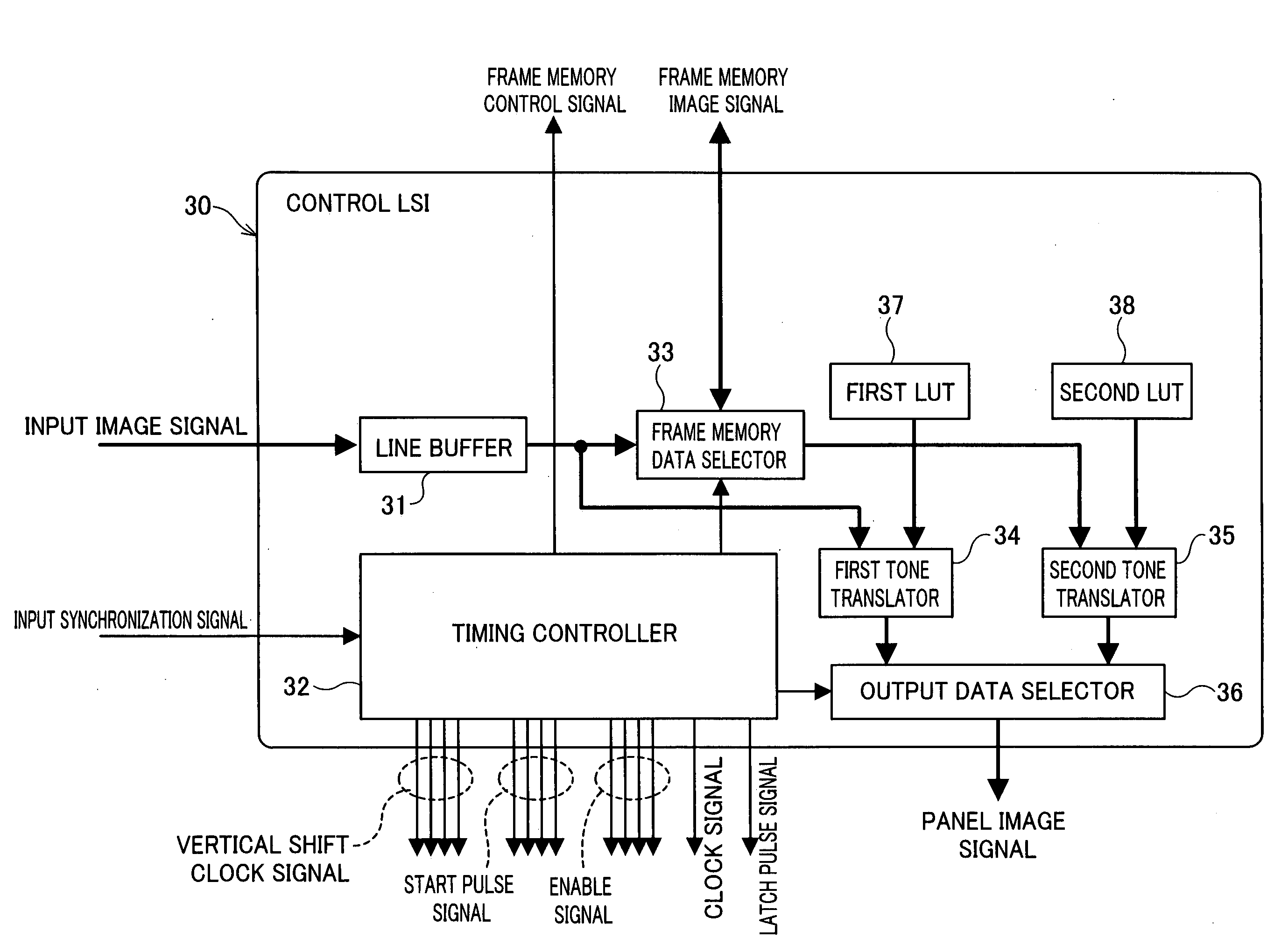
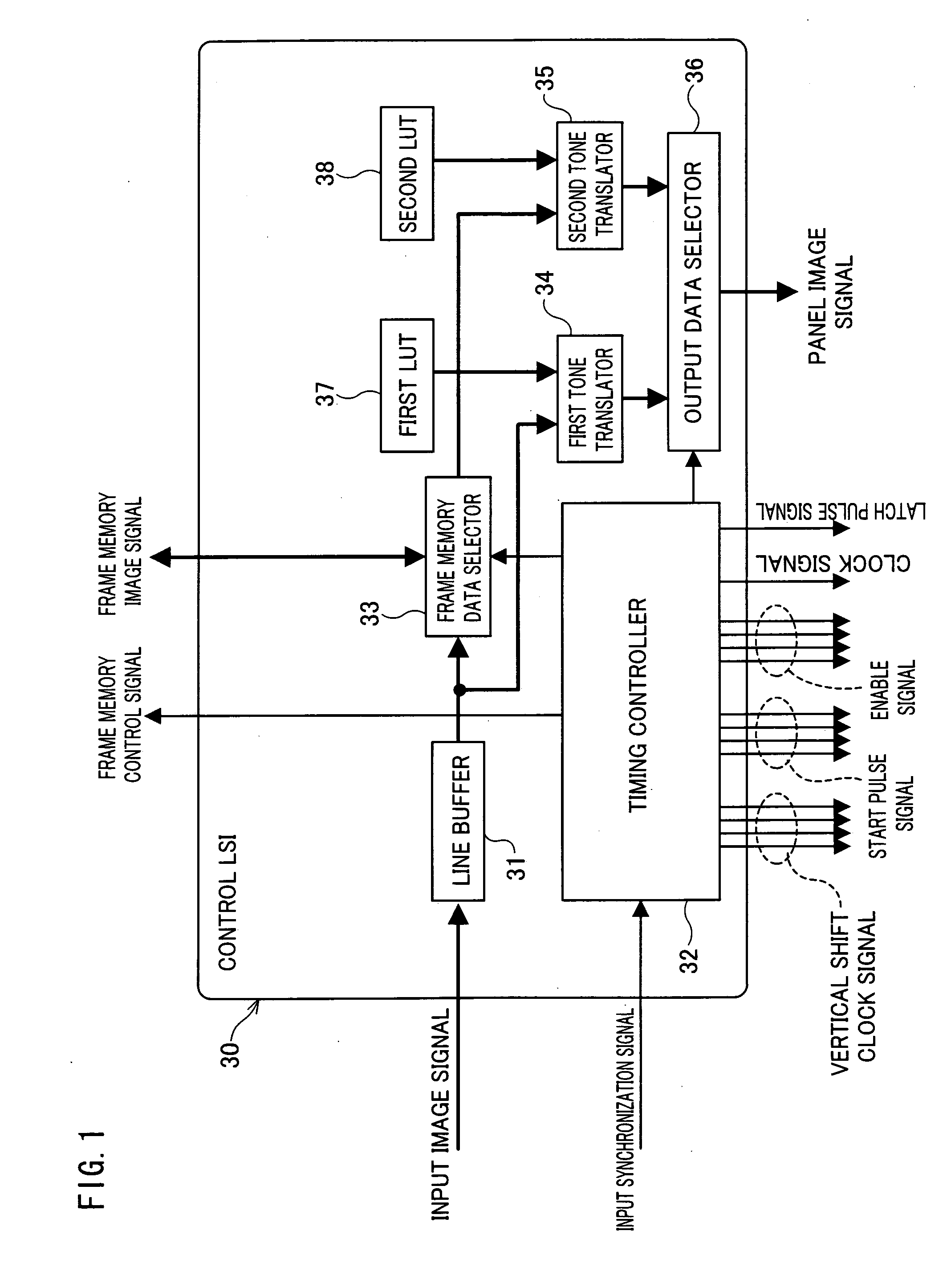
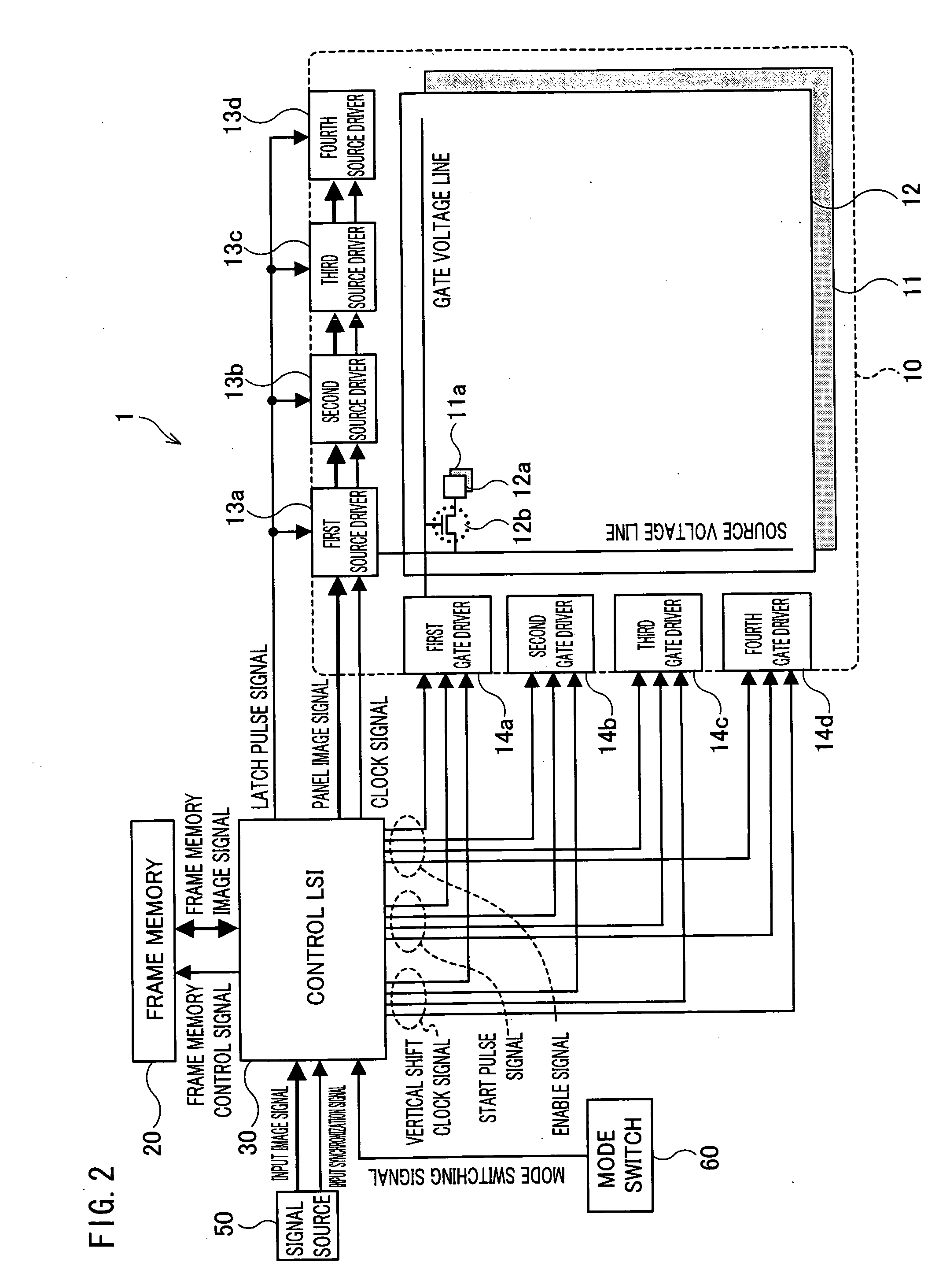
[0037]One embodiment of the present invention is described below with reference to FIG. 1 through FIG. 7. Explained first with reference to FIG. 2 is a schematic arrangement of an image display device according to the present embodiment. In FIG. 2, an image display device 1 includes a display panel 10, a frame memory 20 and a control LSI 30. In the image display device 1, an image can be displayed, in accordance with an input image signal, on the display panel 10. In the case where a device including the image display device 1 is an image display monitor, for example, a signal source 50 serves as a signal input section that transmits an externally input image signal to the image display device 1. In the case where a device including the image display device 1 is a TV (television) receiver, a receiving apparatus that receives television broadcast is used as the signal source 50, and the image display device 1 displays an image in accordance with the television broadcast received by t...


PUM

PropertyMeasurementUnit
frequencyaaaaaaaaaa
luminanceaaaaaaaaaa
frame average luminanceaaaaaaaaaa

Abstract

In one embodiment of the present invention, when an image is displayed in an image display device which has a frequency of 50 to 70 Hz in one frame period, a control LSI is set so that, in the case where the frame average luminance of a pixel is in the range of 150 [cd / m2] to 350 [cd / m2], the contrast ratio between subframe periods is set to: a range of not greater than 50 and not smaller than 1.5 when the luminance is 150 [cd / m2]; a range of not greater than 3.5 and not smaller than 1.5 when the luminance is 200 [cd / m2]; a range of not greater than 2.2 and not smaller than 1.5 when the luminance is 250 [cd / m2]; a range of not greater than 1.8 and not smaller than 1.5 when the luminance is 300 [cd / m2]; 1.5 when the luminance is 350 [cd / m2], and, for a frame average luminance other than the frame average luminance in the range, the contrast ratio is set so as to be monotonously changed between the contrast ratios corresponding to the respective frame average luminance. As a result, flicker visibility can be prevented and moving image blur can be suppressed, thereby realizing an image display device that can display a moving image with high quality.

Description

TECHNICAL FIELD[0001]The present invention relates to image display devices that use a hold-type display element such as a liquid crystal display element or an EL (Electro Luminescence) display element.BACKGROUND ART[0002]In recent years, a variety of display devices have been developed and commercialized, e.g. liquid crystal display devices, plasma display devices, and organic EL display devices, let alone CRT (Cathode-Ray Tube) display devices.[0003]In a display device, such as a CRT display device, that performs an impulse-type display (a display performed only during a light-emitting period), a pixel in its non-selection period provides a black display. On the other hand, in a hold-type display device (a display in which an image of a previous frame is retained until new image data is written) such as a liquid crystal display device or an organic EL display device, a pixel in its non-selection period retains a display content last written (this is a normal display in a hold-type...

Claims


Application Information

Patent Timeline
Patent Type & Authority Applications(United States)
IPC IPC(8): G09G5/10G09G3/34H04N5/44G02F1/133G09G3/20G09G3/36H04N5/66
CPCG09G3/2092G09G3/2096G09G3/3688G09G2360/18G09G2320/0247G09G2320/0285G09G2310/0275
Inventor SHIOMI, MAKOTO
Owner SHARP KK
Learn More