Rotation angle detecting device
a detection device and rotating angle technology, applied in the field of rotating angle detection devices, can solve the problems of inaccurate output signal of magnetic sensors, difficult to accurately position the sensor elements around the permanent magnet rotor, and difficulty in reducing the size of the rotating angle detection device, so as to achieve accurate and compact rotation angle detection
- Summary
- Abstract
- Description
- Claims
- Application Information
AI Technical Summary
Benefits of technology
Problems solved by technology
Method used
Image
Examples
first embodiment
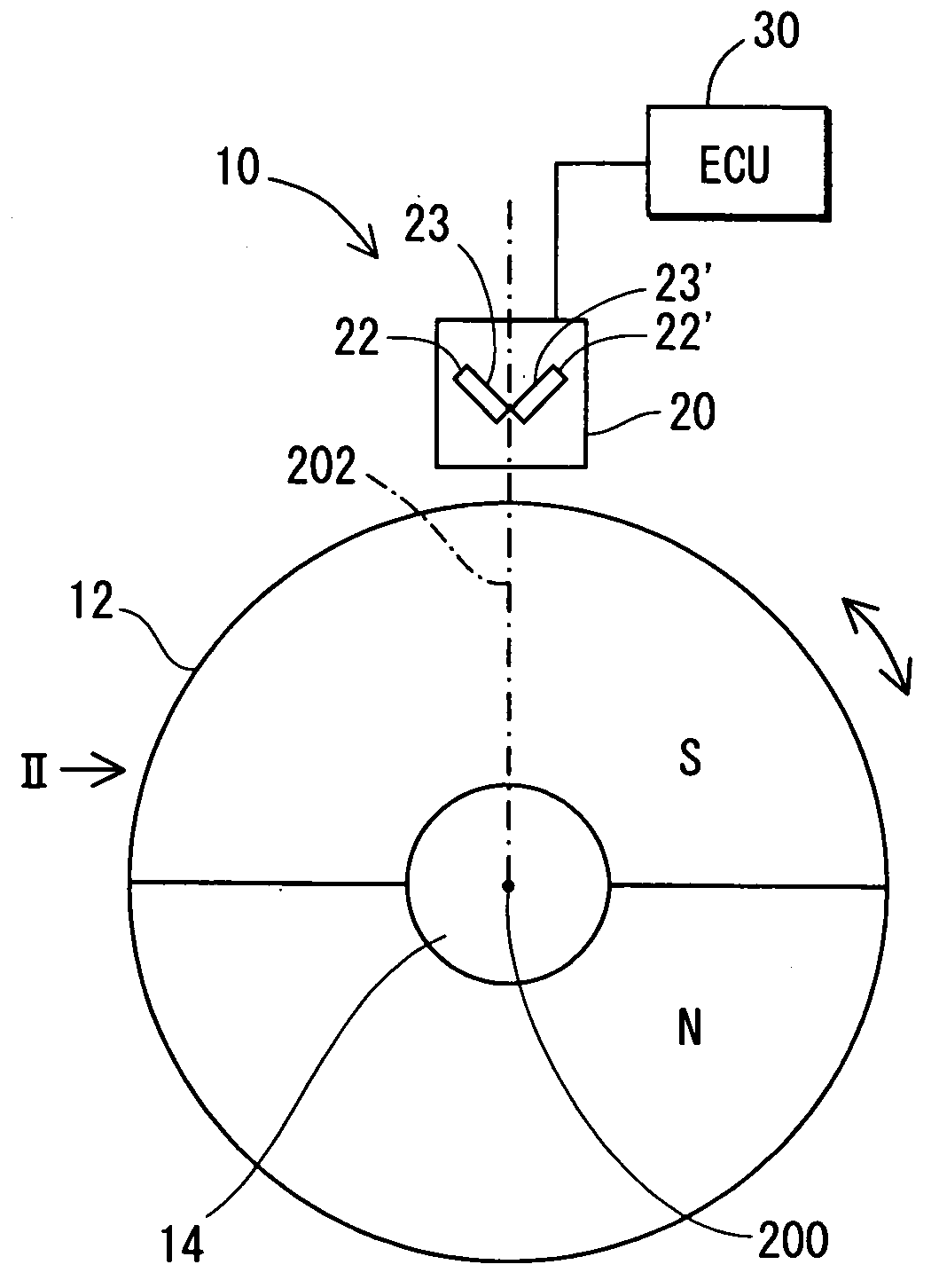
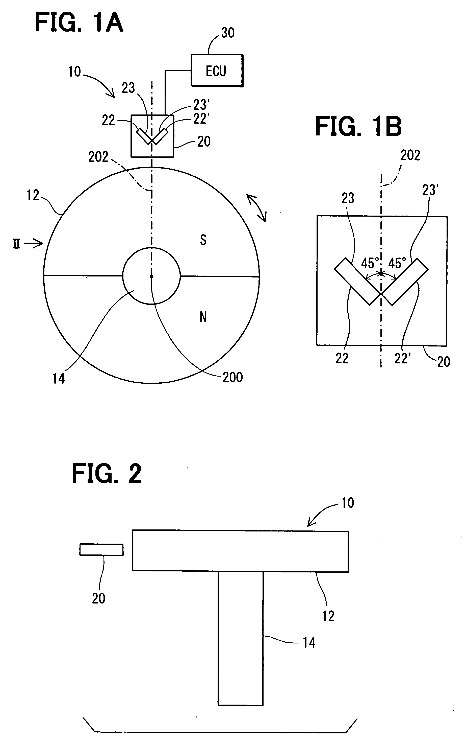
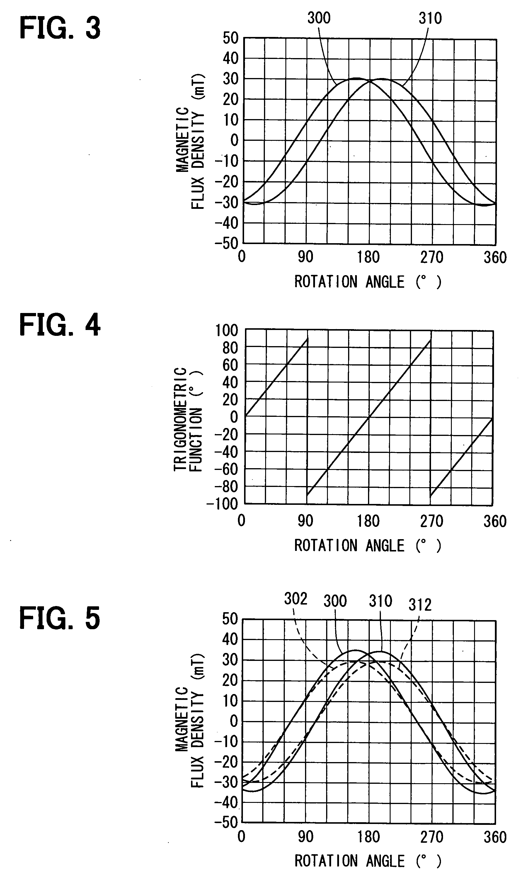
[0056]A rotation angle detecting device 10 according to the invention will be described with reference to FIGS. 1-8.
[0057]The rotation angle detecting device 10 is connected to a rotating object, such as an engine crank shaft or a steering wheel of a vehicle in order to detect the rotation angle of the crankshaft or the steering wheel. The rotation angle detecting device 10 includes a disk-shaped permanent magnet rotor 12, a magnetic sensor (hereinafter referred to as the Hall IC ) 20, and an electronic control unit (hereinafter referred to as ECU ) 30. The permanent magnet rotor 12 is constructed of a pair of semicircular permanent magnets and a rotary shaft 14 that rotates about its rotation axis 200. The permanent magnet rotor 12 is magnetized in a radial direction, as shown in FIG. 18.
[0058]The Hall IC 20 is disposed at a place around the circumference of the permanent magnet rotor 12. The Hall IC 20 includes a pair of Hall elements 22, 22′ and the ECU 30 so as to provide the EC...
second embodiment
[0089]A rotation angle detecting device according to the invention is shown in FIGS. 9A and 9B.
[0090]The rotation angle detecting device 40 includes a pair of Hall elements 22, 22′. Each of the Hall elements 22, 22′ has a magnetic sensor surface 23 or 23′ and is arranged to be on an imaginary plane that is perpendicular to the rotation axis 200 of the permanent magnet rotor 12 so that each of the magnetic sensor surfaces 23, 23′ inclines by 45 degrees in angle toward a normal line 202 that intersects the rotation axis 200 at right angles and so that the magnetic sensor surfaces 23 of the pair of magnetic sensor elements 22 are positioned to have 90 degrees in angle between them. Therefore, the Hall elements 23 are disposed symmetric with respect to the line 202.
[0091]However, the sensor surfaces 23, 23′ are arranged to face the permanent magnet rotor 12, which is opposite to the sensor surfaces of the first embodiment.
[0092]A rotation angle detecting device according to the third em...
fourth embodiment
[0094]A rotation angle detecting device 60 according to the invention is shown in FIGS. 11A and 11B.
[0095]Each of the Hall elements 22, 22′ is disposed in the same manner as the fourth embodiment except that the sensor surfaces 23, 23′ are arranged to face in the opposite direction.
PUM
 Abstract
Description
Claims
Application Information
 - R&D
- Intellectual Property
- Life Sciences
- Materials
- Tech Scout
- Unparalleled Data Quality
- Higher Quality Content
- 60% Fewer Hallucinations
Browse by: Latest US Patents, China's latest patents, Technical Efficacy Thesaurus, Application Domain, Technology Topic, Popular Technical Reports.
© 2025 PatSnap. All rights reserved.Legal|Privacy policy|Modern Slavery Act Transparency Statement|Sitemap|About US| Contact US: help@patsnap.com


