
Gas laser oscillator

a laser oscillator and gas technology, applied in the direction of laser details, electrical apparatus, active medium materials, etc., can solve the problems of inability to obtain the optimal laser output, and inability to determine the composition of laser gas before discharg

Inactive Publication Date: 2008-02-21
FANUC LTD
View PDF3 Cites 23 Cited by
  • Summary
  • Abstract
  • Description
  • Claims
  • Application Information

AI Technical Summary

Benefits of technology

The present invention relates to a gas laser oscillator that can detect the pressure and electric power of the laser gas during operation and determine the kind of laser gas based on these measurements. This is important for ensuring the proper operation and preventing damage or anomalous discharge. Additionally, the invention provides an anomaly judgment means for identifying if the gas laser oscillator is anomalous and an actually measured slope value calculation means for more accurately determining the kind of laser gas. These technical effects improve the accuracy and reliability of the gas laser oscillator.

Problems solved by technology

When the composition of an optimum laser gas is different from the composition determined in advance and / or the pressure setting of the laser gas in the gas laser oscillator is different from the pressure setting determined in advance, it is not possible to obtain an optimum laser output.
Publication (Kokai) No. 2001-44534, it is necessary to generate discharge voltage in order to adjust the composition of the laser gas, and therefore, it is not possible to determine the composition of the laser gas before discharge.
In addition, in Japanese Unexamined Patent Publication (Kokai) No. 2001-44534, it is necessary to cause a discharge to occur each time the composition of the laser gas is determined, and therefore, the laser power supply and / or the discharge tube may gradually deteriorate due to the discharge.
Further, when the composition of the laser gas is different from the composition determined in advance, an anomalous discharge may occur and the laser power supply and / or the discharge tube may quickly deteriorate.

Method used


Image

  • Gas laser oscillator
  • Gas laser oscillator
  • Gas laser oscillator

Examples


Embodiment Construction

[0030]The embodiments of the present invention are explained below with reference to the accompanied drawings. In the following drawings, the same members are assigned like reference numerals, and for easier understanding, the scale of these drawings has been adjusted appropriately.

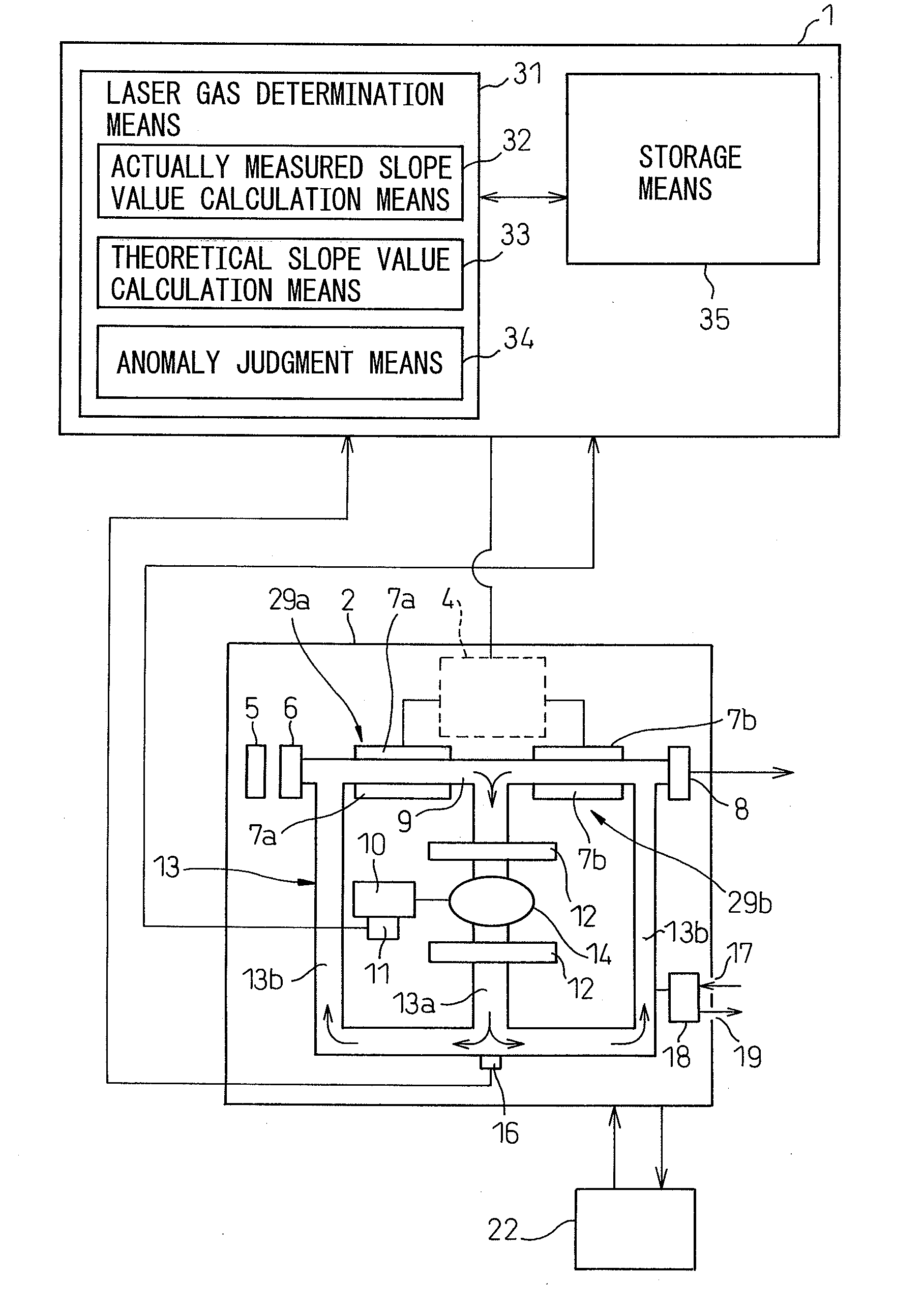
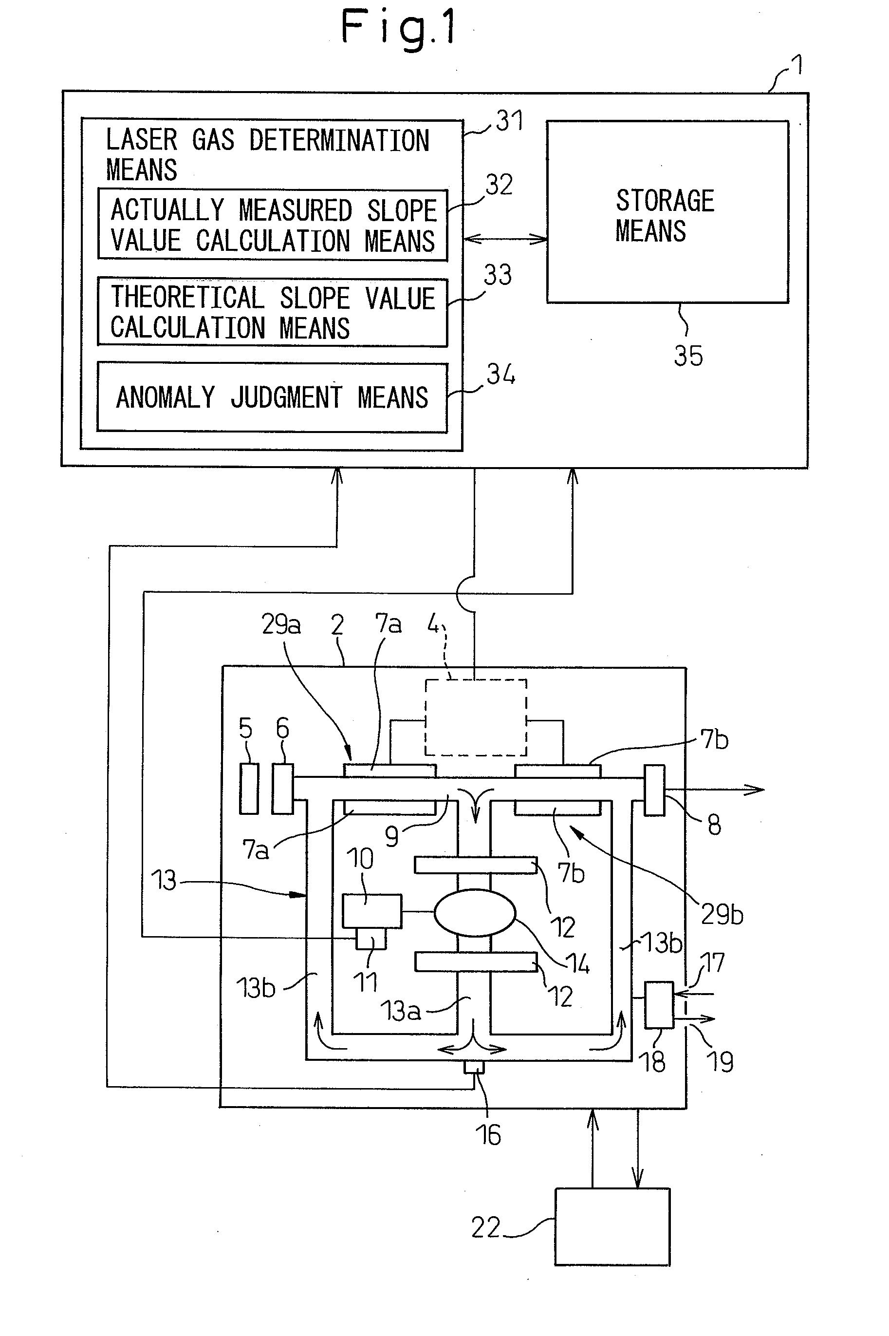
[0031]FIG. 1 is a schematic diagram of a gas laser oscillator according to the present invention. A laser oscillator 2 in the present invention is a gas laser oscillator of a discharge excitation type with a comparatively high output, for example, a carbon dioxide gas laser with an output of 2 kW or greater. The laser oscillator 2 includes a circulation path 13. As shown schematically, the circulation path 13 comprises a discharge tube 9, a suction pipe path 13a that sucks a laser gas from substantially the central portion in the longitudinal direction of the discharge tube 9, and a return pipe path 13b for discharging the laser gas to the portions adjacent to both end portions of the discharge tube 9.

[00...


PUM


Abstract

A gas laser oscillator (2) that excites a laser gas to generate laser light includes a circulation path (9) for the laser gas, a circulation means (14) for circulating the laser gas through the circulation path, a pressure detection means (16) for detecting the pressure of the laser gas in the circulation path, an electric power detection means (11) for detecting electric power to drive the circulation means, a storage means (35) for storing the relationship between the pressure of the laser gas and the electric power of the circulation means during the period of normal operation of the circulation means for each kind of the laser gas, and a laser gas determination means (31). The laser gas determination means determines the kind of the laser gas based on the pressure of the laser gas and the electric power of the circulation means detected during the period of normal operation of the circulation means, and the relationship between the pressure of the laser gas and the electric power of the circulation means stored in the storage means. Due to this, the laser gas is determined without generating a discharge voltage. If the laser gas cannot be determined, it may be possible to judge that the laser oscillator is anomalous.

Description

BACKGROUND OF THE INVENTION[0001]1. Field of the Invention[0002]The present invention relates to a gas laser oscillator that excites a gas to obtain laser output.[0003]2. Description of the Related Art[0004]A general gas laser oscillator excites a laser gas sealed in a discharge tube by discharge energy between discharge electrodes, and generates laser light having an oscillation wavelength corresponding to the amount of energy emitted when a molecule or atom of the gas in the excited state transits to a lower energy level.[0005]In such a gas laser oscillator, an optimum composition of a laser gas is determined in advance. Then, the pressure of the laser gas in the gas laser oscillator is set to be optimum based on the laser gas having that composition.[0006]When the composition of an optimum laser gas is different from the composition determined in advance and / or the pressure setting of the laser gas in the gas laser oscillator is different from the pressure setting determined in a...

Claims


Application Information

Patent Timeline
Patent Type & Authority Applications(United States)
IPC IPC(8): H01S3/22
CPCH01S3/036H01S3/0407H01S3/041H01S3/2232H01S3/097H01S3/10069H01S3/134H01S3/073
Inventor EGAWA, AKRAKOBAYASHI, EIJIWATANABE, TAKESHI
Owner FANUC LTD
Learn More