
Medical device for vessel compatibility during high pressure infusion

a medical device and high-pressure infusion technology, applied in the field of delivery, can solve the problems of high cell engraftment, achieve the effects of reducing the risk of trauma or damage, increasing the pressure, and limiting conta

Inactive Publication Date: 2008-02-14
BOSTON SCI SCIMED INC
View PDF1 Cites 87 Cited by
  • Summary
  • Abstract
  • Description
  • Claims
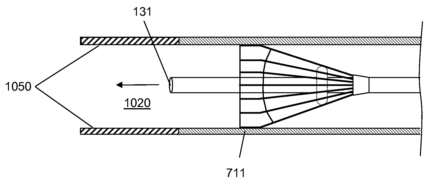
  • Application Information

AI Technical Summary

Benefits of technology

[0006]The invention provides devices that can be used to deliver a therapeutic agent to a treatment site within the vessel of a patient at increased pressure, while limiting the contact with and pressure placed on the vessel walls. Hence a bolus of therapeutic agent may be delivered with decreased risk of trauma or damage to the treatment site. Additionally, the invention provides for large lumen diameters, decreasing the risk of damage to the therapeutic agent being delivered due to shear stresses.
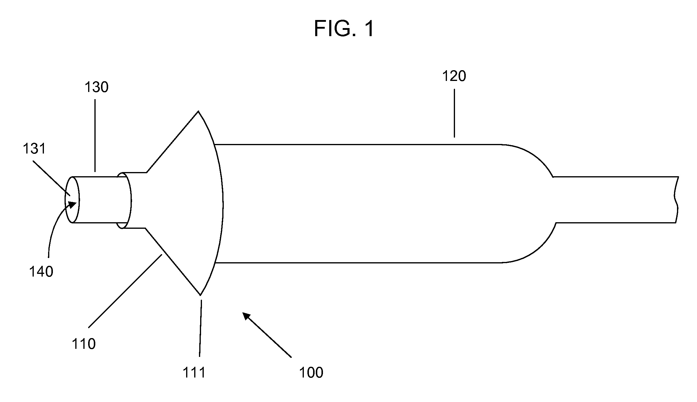
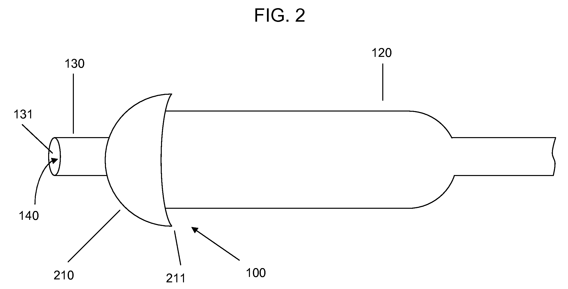
[0007]A device is provided that comprises a tube having a lumen and an expandable structure capable of sealing or obstructing fluid flow through the vessel near the treatment site. When the device is positioned at an intended treatment site, the expandable structure may be expanded by an operator of the device. The structure may be expanded to a size and with sufficient pressure to obstruct or occlude the flow of blood within the vessel. In certain embodiments, when the expandable structure is expanded, only a relatively small portion of the expandable structure will contact the vessel wall. For example, in certain embodiments the structure may contact the vessel along a length of about 1 mm or less. A bolus of therapeutic agent may be delivered under high pressure, via the lumen, and the expandable structure serves to substantially prevent backflow of the therapeutic agent.
[0008]It is believed that some therapeutic agents may be more effective if delivered under at least approximately physiologic pressure. For example, achieving physiologic pressure in the coronary vasculature may result in higher cell engraftment when the therapeutic agent being delivered includes a cell slurry. The expandable structure may substantially prevent backflow of the therapeutic agent, by providing sufficient pressure against the vessel wall to prevent collapse of the structure by the therapeutic agent being injected.
[0009]To accommodate high-pressure delivery, and also to prevent problems such as clogging of the lumen by therapeutic agents such as cell slurries, the invention may incorporate lumens of large diameter. The lumen may be, for example, at least about 0.5 mm in diameter.
[0010]In some embodiments, a sheath may be placed around the expandable structure to protect the expandable structure during insertion and positioning of the device within a vessel. For example, the expandable structure may be collapsed and the sheath positioned over and around the expandable structure. When the device is positioned at an intended delivery site, an operator of the device may retract the sheath or push the expandable structure out of the sheath. In such an embodiment, the expandable structure may be self-expanding such that removal of the sheath allows the expandable structure to spring open or self-expand. After a therapeutic agent has been delivered, the sheath may be repositioned over the structure to allow the device to be removed from the vessel.

Problems solved by technology

For example, achieving physiologic pressure in the coronary vasculature may result in higher cell engraftment when the therapeutic agent being delivered includes a cell slurry.

Method used


Image

  • Medical device for vessel compatibility during high pressure infusion
  • Medical device for vessel compatibility during high pressure infusion
  • Medical device for vessel compatibility during high pressure infusion

Examples


Embodiment Construction

[0021]Devices according to the invention comprise a tube having a lumen and an expandable structure capable of obstructing or occluding a vessel near a desired treatment site. When such a device is positioned at an intended treatment site, the expandable structure may be expanded by an operator of the device. While expanded, generally only a relatively small portion of the expandable structure will contact the vessel wall. In certain embodiments, the structure contacts the vessel along a length of about 1 mm or less. It is believed that such reduction in contact with the vessel may reduce the likelihood of injury to tissue or reinjury to damaged tissue. Once there is substantially no blood flow in the region of the treatment site, a bolus of therapeutic agent may be delivered via the lumen. The expandable structure can prevent or minimize backflow of the therapeutic agent. After delivery of the therapeutic agent, the expandable structure may then be contracted, and the device withdr...


PUM


Abstract

The invention provides devices that can be used to deliver a therapeutic agent to a treatment site within the vessel of a patient at increased pressure, while limiting the contact with and pressure placed on the vessel walls. Devices according to the invention include an expandable structure arranged around and on a tube having a lumen. The expandable structure may include a sealing ring that makes contact with the interior surface of a vessel to prevent or decrease fluid flow during delivery of a therapeutic agent. This allows delivery of a therapeutic agent with decreased risk of injury to the treatment site. The invention also provides for large lumen diameters, preventing shearing stress on therapeutic agents such as cell slurries.

Description

CROSS-REFERENCE[0001]This application is related to application number U.S. 60 / 836,656 filed on Aug. 10, 2006, in the U.S. and claims priority to this application, which is incorporated herein by reference in it's entirety.TECHNICAL FIELD[0002]The present invention relates to the delivery of a therapeutic agent or other material to a treatment site.BACKGROUND[0003]Delivery of therapeutic agents to the interior of vessels is a growing field of interest. For example, adverse remodeling of the myocardium and associated long-term damage may be reduced or prevented by delivering mesenchymal stem cells after stent reperfusion following a myocardial infarction. This and other treatments are performed by positioning a standard angioplasty balloon near the treatment site. A balloon may be placed, for example, at the site of previous stenting. The balloon is inflated at or near the desired treatment site, and inflated to a pressure sufficient to seal the vessel and prevent blood flow. The gui...

Claims


Application Information

Patent Timeline
Patent Type & Authority Applications(United States)
IPC IPC(8): A61M25/10A61F2/958
CPCA61B17/12022A61B17/12104A61B17/12131A61B17/12172A61B2017/1205A61B17/1204A61M2025/0024A61M2025/1052A61M2025/1081A61M2025/1095A61M29/02
Inventor EPSTEIN, SAMUEL J.FREYMAN, TOBYHARRIS, CHAD G.MICKLEY, TIMOTHY J.
Owner BOSTON SCI SCIMED INC
Learn More