Bicycle golf bag

a golf bag and bicycle technology, applied in the field of bicycle golf bags, can solve the problems of difficult balance of bicycles, unbalanced load, and possible obstruction of objects, and achieve the effect of further stability during transportation

Inactive Publication Date: 2008-02-14
LOSOS JERRY T
View PDF18 Cites 10 Cited by
  • Summary
  • Abstract
  • Description
  • Claims
  • Application Information

AI Technical Summary

Benefits of technology

[0004] One object of the invention is to provide at least partially bifurcated golf bag assembly that can be easily and securely mounted on a bicycle.
[0005] Another object of this invention is to provide cylindrical tubes and plates to separate and maintain the position of the golf clubs in the bag and balance and stabilize the clubs during transport.
[0006] Another object of this invention is to provide for easy identification removal of the golf clubs from the bag accomplished by positioned cylindrical tubes.
[0007] Another object of the invention is to provide a lightweight golf bag that is stable and can stand in an upright position with additional supporting means.
[0008] Another object of this invention is to provide for a low center of gravity with the bag on the bicycle for stable, unbalanced and safe transport of bag and operator.
[0010] Another object of this invention is to provide attachments to the golf bag that are removable and that can be positioned on the handlebars of the bicycle to provide for further stability during transport.

Problems solved by technology

Golf bags however cannot be easily transported on a bicycle since it is difficult to secure existing golf bags to the bicycle so that the golf bag does not interfere with the operator, the operation and / or mechanisms of the bicycle or objects on the route.
The weight and size of the golf bag on the bicycle make the bicycle difficult to balance.
A rod with brackets for receiving a golf bag is attached to one side of the bicycle resulting in the golf bag extending out from one side of the bicycle creating an unbalanced load and a possible obstruction to the objects on the route.
Placing the golf bag weight in this fashion, high on the riders back, raises the center of gravity making it more difficult for the operator to balance on the wheels.

Method used


Image

  • Bicycle golf bag
  • Bicycle golf bag
  • Bicycle golf bag

Examples


Embodiment Construction

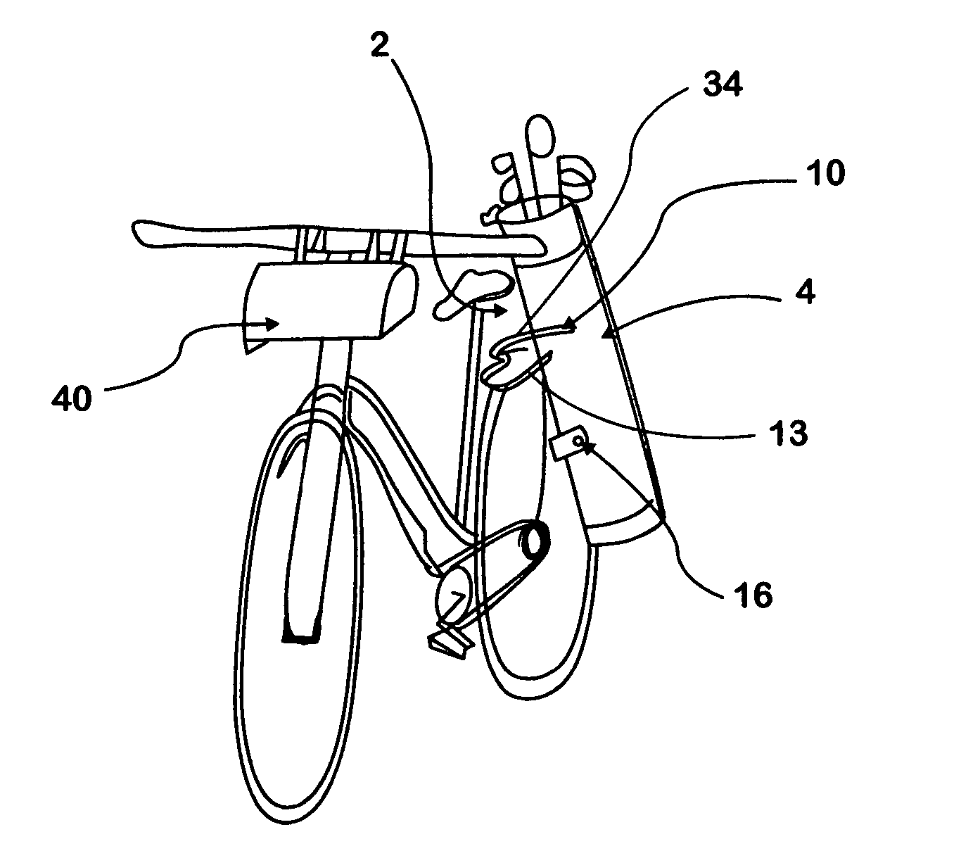
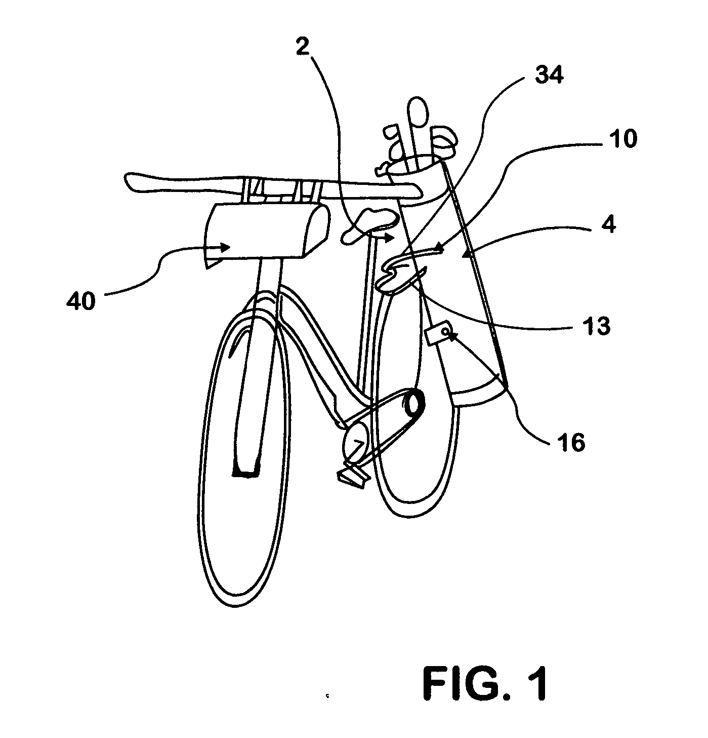
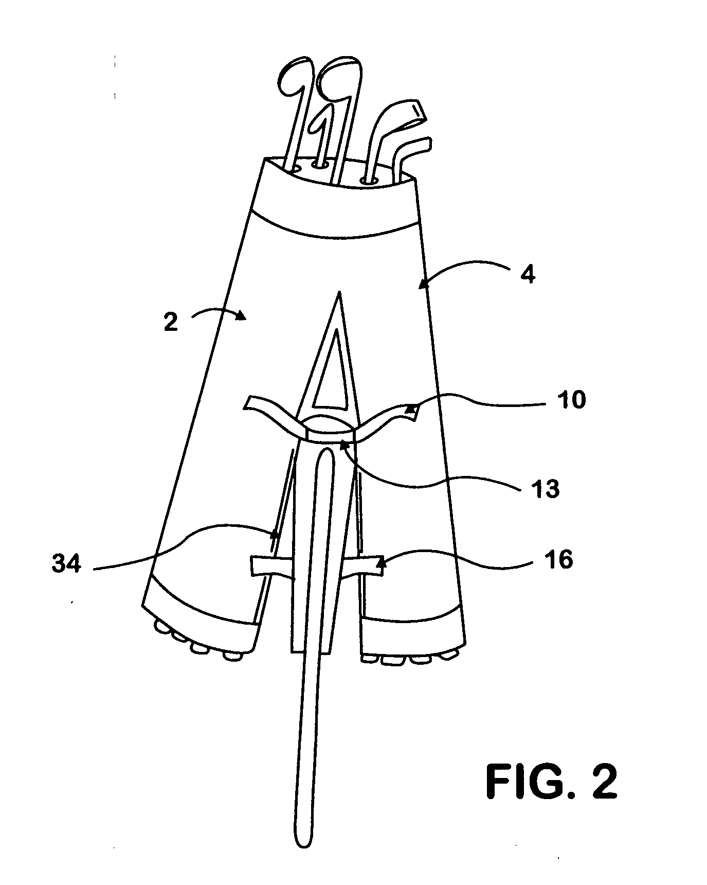
[0018] In FIGS. 1 and 2 there is shown the golf bag assembly comprising of the first bag portion 2 and second bag portion 4 secured by means of releasable fasteners 10 to the front and rear of the bicycle rack 13 and by releasable fasteners 16 to the side of the bicycle rack 13 and supported on the bicycle rack by flexible webbed strap 34. The shoe / equipment bag 40, which is further described below in FIG. 7, is secured to the handlebars of the bicycle. Where the term “bicycle” is used in the application, that term includes bicycle, scooter, motorcycle and any other two wheeled vehicle with the wheels in line.

[0019]FIG. 3 there is shown the lightweight material providing the exterior covering 18 for a first and second bag portions 2,4. The cyclical tubes 20 receive the golf clubs 22. The tubes 20 are maintained in position by holes 24 in a series of semicircular plates 26 throughout the gag portions 2 and 4. The rims 28 on the top of the tubes 20 keep the tubes 20 from passing thro...


PUM


Abstract

A bifurcated golf bag assembly with attachments that can be carried securely on a two wheeled vehicle such as a bicycle. The golf bag assembly includes a first and second bag each containing a number of rimmed cylindrical tubes forming receptacles for receiving golf clubs, a series of semicircular plates with a number of holes similarly positioned in each of the plates to receive, separate and maintain the position of the cylindrical tubes in the bags. The bag portions are joined at the top by a plate comprised of two semicircular plates joined at the center by a hinge assembly to allow the bags to pivot away from each other to opposite sides of a bicycle rack. The bag assembly is supported on the bicycle rack by angled straps and secured by releasable fasteners that fasten the bag portions together when not in transport.

Description

[0001] This application is a United States Non-Provisional application based upon and claiming the priority and filing date of U.S. Provisional Patent Application, Ser. No. 60 / 796,494, filed May 1, 2006. This invention relates to a golf bag assembly with attachments that splits so that it can be easily and safely transported on a two wheeled vehicle such as a bicycle.BACKGROUND OF THE INVENTION [0002] Golf bags are the conventional means for transporting golf clubs. Golf bags however cannot be easily transported on a bicycle since it is difficult to secure existing golf bags to the bicycle so that the golf bag does not interfere with the operator, the operation and / or mechanisms of the bicycle or objects on the route. The weight and size of the golf bag on the bicycle make the bicycle difficult to balance. There exist devices which enable golf bags to be attached to bicycles, an example being U.S. Pat. No. 5,340,003. A rod with brackets for receiving a golf bag is attached to one si...

Claims


Application Information

Patent Timeline
Patent Type & Authority Applications(United States)
IPC IPC(8): A63B55/00
CPCA63B55/00B62J9/001B62J9/00A63B55/08A63B55/40A63B55/60B62J9/21B62J9/23B62J9/24B62J9/27B62J11/05
Inventor LOSOS, JERRY T.
Owner LOSOS JERRY T
Why Eureka
Try Eureka