
Tissue dispenser

a tissue dispenser and dispenser box technology, applied in the field of tissues dispensers, can solve the problems of not having an appropriate surface on which to mount this traditional sized tissue dispenser, the difficulty of storing a tissue dispenser box stationary in a moving vehicle, and the inability to meet the needs of us

Inactive Publication Date: 2008-02-14
WAY MARJORIE MOORE
View PDF18 Cites 8 Cited by
  • Summary
  • Abstract
  • Description
  • Claims
  • Application Information

AI Technical Summary

Problems solved by technology

It is difficult to hold a tissue dispenser box stationary in a moving vehicle with the tissues within reach of the driver.
There may be no convenient surface near the use upon which the tissue dispenser may be placed.
A drawback of this approach is that there may not be an available and appropriate surface on which to mount this traditional sized tissue dispenser.
Once again, a drawback of this approach is that there may not be an available and appropriate surface on which to mount this traditional sized tissue dispenser.
Also, smaller packages that dispense tissues, that can be carried in a purse or the like, typically come in a rectangular soft package that may be difficult to use and store.

Method used


Image

  • Tissue dispenser
  • Tissue dispenser
  • Tissue dispenser

Examples


Embodiment Construction

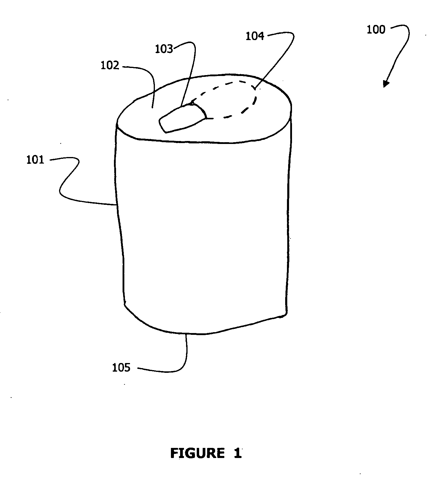
[0025]FIG. 1 is a sketch of a tissue dispenser 100 according to some embodiments of the present invention. The main body 101 of the tissue dispenser 100 is predominantly cylindrical in shape. The main body 101 is adapted to fit snugly into a cup or can holder of a motor vehicle. Many of the cup holders in modern vehicles are sized such that they fit snugly with a friction fit against a standard sized soft drink can. This is typically a diameter of 2 and ½ inches to 2 and ⅝ inches in diameter. By mounting the tissue dispenser in a cup holder, the tissue dispenser is both securely mounted and within ready reach of the user.

[0026]The main body 101 has a bottom surface 105 and a top surface 102. In some embodiments, the top surface will be the surface through which tissues stored within the tissue dispenser 100 are removed. A pull tab 103 may be mounted onto the top surface 102. The pull tab 103 is mounted to a tear portion 104 of the top surface 102 which is surrounded by a serrated, o...


PUM


Abstract

A tissue dispenser adapted to mount into the cup holders of a modern vehicle. A tissue dispenser comprising all recyclable products. A tissue dispenser adapted to mount into the cup holder of a vehicle with refillable tissue package inserts. A method for folding tissues for dispensing from a cylindrical dispenser. A portable tissue dispenser adapted to be carried in a purse or the like.

Description

BACKGROUND[0001]1. Field of the Invention[0002]This invention relates to dispensers for tissues, and more specifically to a dispenser intended for use in vehicles.[0003]2. Description of Related Art[0004]It is difficult to hold a tissue dispenser box stationary in a moving vehicle with the tissues within reach of the driver. The dispenser tends to move about in response to movements of the vehicle. There may be no convenient surface near the use upon which the tissue dispenser may be placed.[0005]U.S. Patent Application No. US2003 / 0213810 A1 to Wu discloses a tissue dispenser with an attachment mechanism secured to the bottom for attaching the tissue dispenser to a support surface. A drawback of this approach is that there may not be an available and appropriate surface on which to mount this traditional sized tissue dispenser.[0006]U.S. Patent Application No. US2001 / 0019072 A1 to Wu discloses another tissue dispenser with an attachment means for securing the box holder in a desired...

Claims


Application Information

Patent Timeline
Patent Type & Authority Applications(United States)
IPC IPC(8): B65H1/00
CPCA47K10/421A47K10/3818
Inventor WAY, MARJORIE MOORE
Owner WAY MARJORIE MOORE
Learn More