Eureka AIR delivers breakthrough ideas for toughest innovation challenges, trusted by R&D personnel around the world.

Adjustable-installed recessed lighting

a technology of recessed lighting and adjustable installation, which is applied in the direction of fixed installation, lighting and heating equipment, lighting support devices, etc., can solve the problems of deteriorating installation effect and complex installation, and achieve the effect of simple and fixed installation, facilitation of installation and simple structur

Inactive Publication Date: 2008-02-07
SHEN TIANLIN
View PDF7 Cites 5 Cited by
  • Summary
  • Abstract
  • Description
  • Claims
  • Application Information

AI Technical Summary

Benefits of technology

[0008]One object of the invention is to provide an adjustable-installed recessed lighting in which the spring leaf can be easily adjusted for its installation position so that an excellent installation effect may be realized. It needn't change the install spring leaf having different length or shape and adjust the installation by the screw machine.
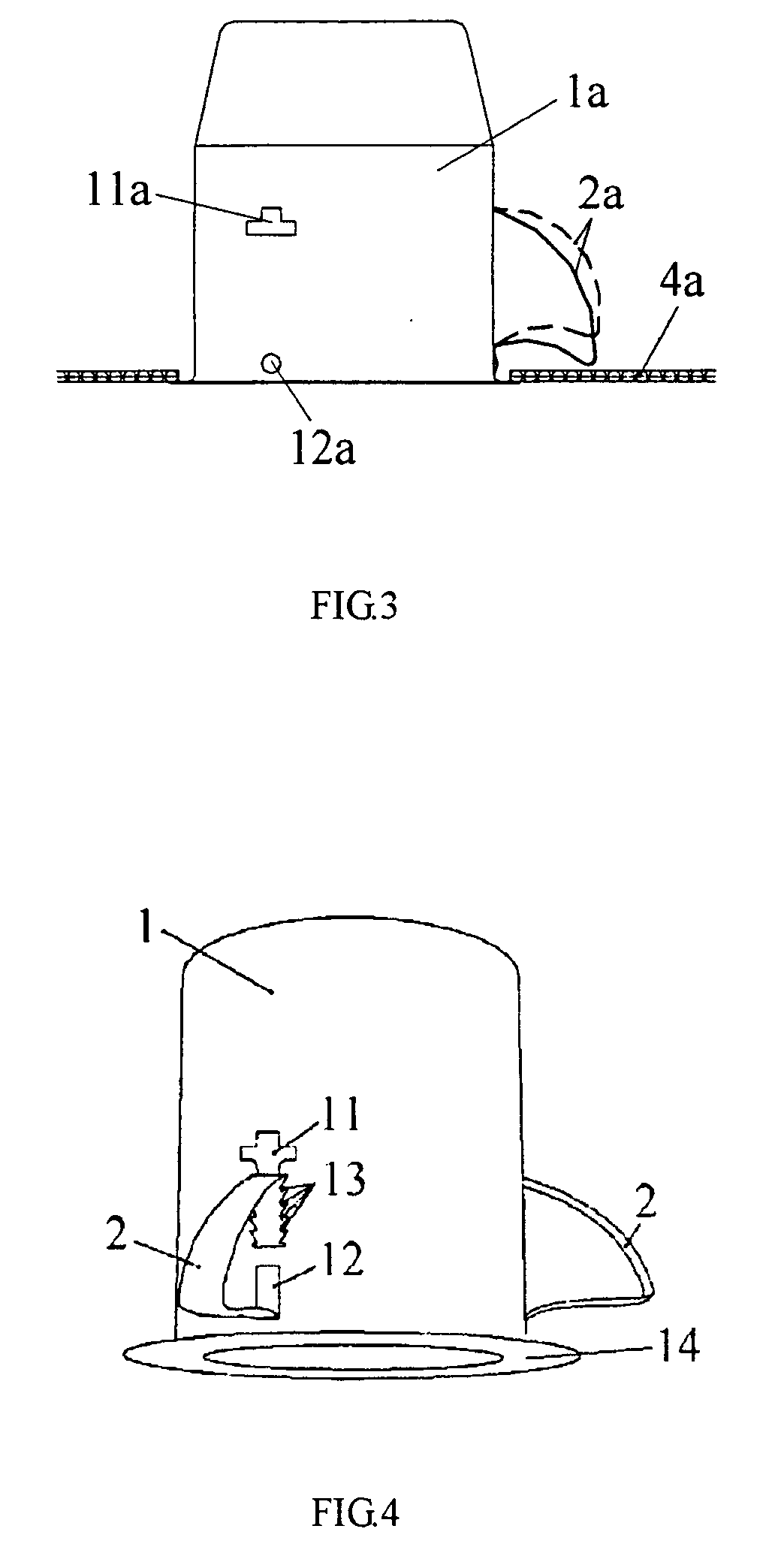
[0013]The invention has the following advantages: since the support hole has multilevel clamping openings, the top end of the spring leaf may be inserted into the clamping opening with different height depending on the thickness of the installation wall; because of the setting of the slip holes, the spring leaf can keep the same bend for the different thickness of the installation wall so that the installation of the lighting is facilitated, simple and fixed, without changing for the spring leaf with different length or shape depending on the thickness of the installation wall, and without adjusting with the installation by the screw machine.

Problems solved by technology

If not, the effect of the installation is deteriorated.
In this case, the installation is more complex.

Method used


Image

  • Adjustable-installed recessed lighting
  • Adjustable-installed recessed lighting
  • Adjustable-installed recessed lighting

Examples


Embodiment Construction

[0023]The preferred embodiments of the invention will be explained by reference to the accompanying drawings.

[0024]As shown in FIGS. 4-6, the adjustable-installed recessed lighting of the invention comprises a lighting body 1 and a spring leaf 2. A support hole 11 and a slip hole 12 located below the support hole are arranged on the lighting body 1, wherein the support hole 11 comprises the multilevel clamping opening 13 along the height direction; the top end 21 of said spring leaf 2 is inserted in one higher clamping opening 13. As shown in FIG.4, the top end 21 is inserted in the higher clamping opening 13 when the installation wall is thick. As shown in FIG. 7, the top end 21 is inserted in the middle clamping opening 13. Of course, the lower clamping opening 13 will be used if the installation wall is very thin. The bottom end 22 of the spring leaf 2 can self-move to adapt its bending degree depending on the thickness of the installation wall, so that the bottom end 22 can self...


PUM


Abstract

The invention provides an adjustable-installed recessed lighting including a lighting body on which a support hole is arranged; a spring leaf having the top end recessed by the support hole and a bottom end; wherein, a sliding chute located below the support hole is arranged on the lighting body; said support hole has multilevel clamping openings along the direction of the height; the top end of said spring leaf is inserted in the clamping opening and the bottom end may slide in the sliding chute. Since the support hole has multilevel clamping openings, the top end of the spring leaf may be inserted in the clamping opening with different height depending on the thickness of the installation wall; because of the setting of the sliding chutes, the spring leaf can keep the same bend for the different thickness of the installation wall so that the installation of the lighting is facility, simple and fastness.

Description

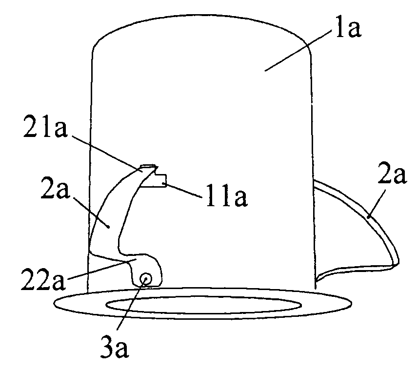
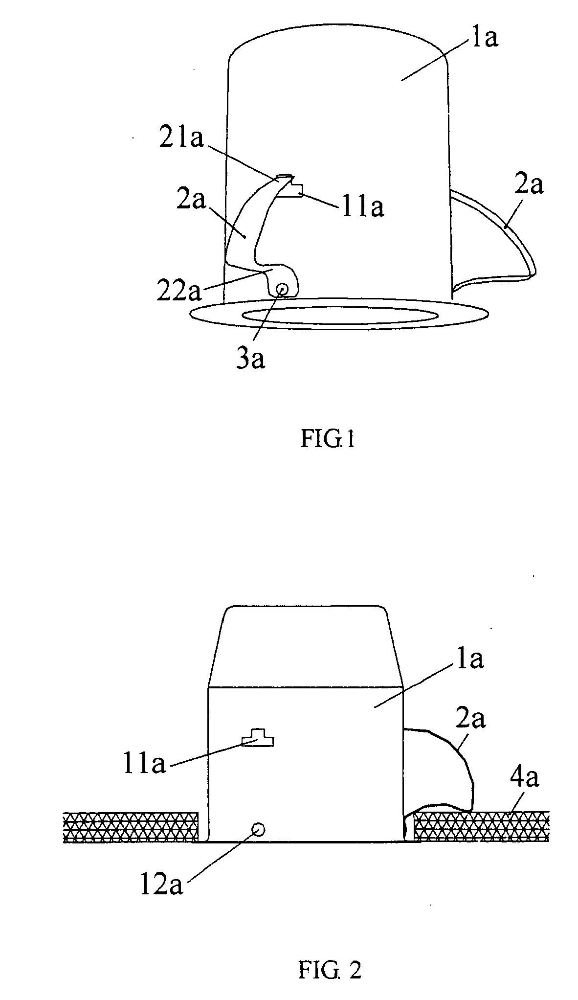
CROSS-REFERENCE TO RELATED APPLICATIONS[0001]The present application claims priority under 35 USC 119 to Chinese Patent Application No. 200620044528.X filed on Aug. 3, 2006 the entire contents of which are hereby incorporated by reference.BACKGROUND OF THE INVENTION[0002]1. Technical Field[0003]The invention relates generally to a recessed lighting, specially to an adjustable-installed recessed lighting.[0004]2. Description of Background Art[0005]A present recessed lighting shown in FIGS. 1-3 comprises a lighting body 1a on which a support hole 11a and a fix hole 12a below the support hole are arranged, and a spring leaf 2a having a top end 21a and a bottom end 22a. A cut-out (not shown) on the neck of the top end 21a is inserted in the support hole 11a. The bottom end 22a is fixed in the fix hole 12a by a bolt or a rivet 3a passing through a mounting hole arranged thereon (not shown), such that it can't move freely.[0006]When a lighting is installed, for example, in the ceiling, th...

Claims


Application Information

Patent Timeline
IPC IPC(8): F21V15/01F21V21/04
CPCF21V21/04
Inventor SHEN, TIANLIN
Owner SHEN TIANLIN
Why Eureka
Eureka Blog
Learn More