Method and apparatus for using an infrared reflectivity sensor in a security system

a technology of infrared reflectivity and security system, applied in the field of door proximity sensors, can solve the problems of limited knowledge and each of these sensors being defeated

Active Publication Date: 2008-02-07
JOHNSON CONTROLS TYCO IP HLDG LLP
View PDF24 Cites 16 Cited by
  • Summary
  • Abstract
  • Description
  • Claims
  • Application Information

AI Technical Summary

Problems solved by technology

Unfortunately, each of these sensors may be defeated by a person having limited knowledge of the sensor and / or security system.
Sunlight may also cause interference.

Method used


Image

  • Method and apparatus for using an infrared reflectivity sensor in a security system
  • Method and apparatus for using an infrared reflectivity sensor in a security system
  • Method and apparatus for using an infrared reflectivity sensor in a security system

Examples


Embodiment Construction

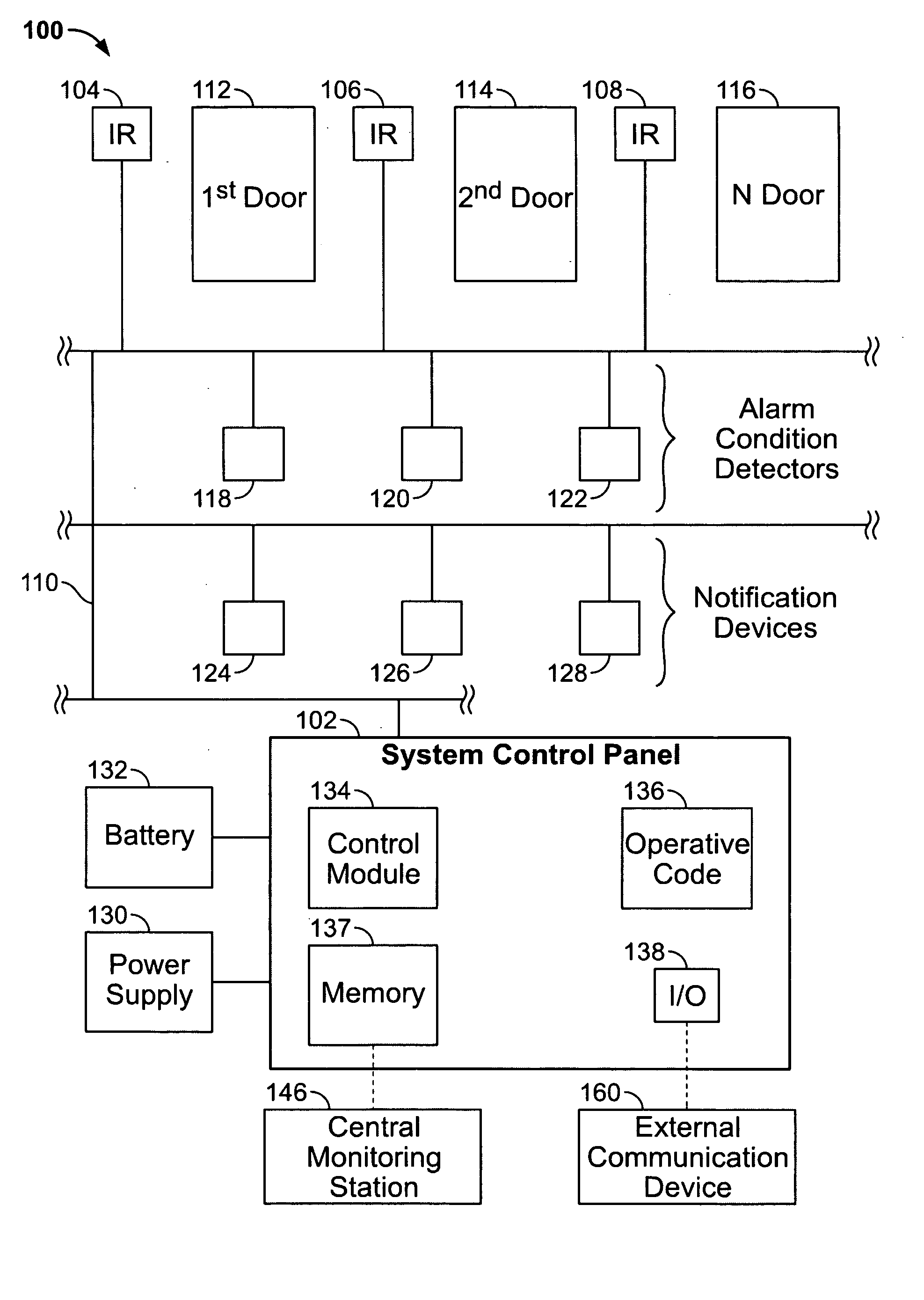
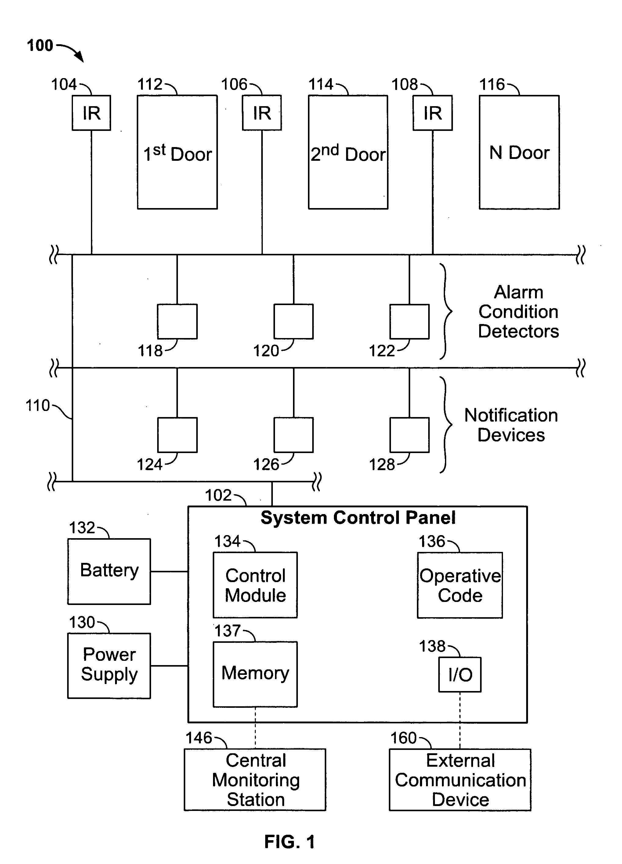
[0016]FIG. 1 illustrates a security system 100 which has a system control panel 102 for monitoring and / or controlling devices installed on a network 110. The devices may detect and / or control door openings and closings, detect alarm conditions, notify people within an area about alarm conditions, track and / or control temperature, or accomplish other functions which may be desired. For example, the system 100 may be used within a light industrial building or a residence.

[0017]The system 100 has one or more infrared (IR) sensors, such as first IR sensor 104, second IR sensor 106 and N IR sensor 108 connected to the network 110 and in communication with the system control panel 102. The first, second, through N IR sensors 104-108 may be configured to control and / or monitor a first door 112, second door 114, through N door 116, respectively. The first through N IR sensors 104-108 may receive power from, and communicate with, the system control panel 102 over the network 110. Each of the...


PUM


Abstract

The IR sensor is configured to be mounted proximate to a door to be monitored. The IR sensor has an IR transmitter and an IR receiver. The IR transmitter has an active period and an idle period. The IR transmitter transmits control data packets which are provided by the processor during the active period. The IR receiver has an active period for detecting IR data and reflected data packets. Each of the reflected data packets has a packet IR reflectivity. The memory stores a door IR reflectivity associated with a door surface of the door, and the processor compares the packet IR reflectivity to the door IR reflectivity to determine at least a door position of the door.

Description

BACKGROUND OF THE INVENTION[0001]This invention relates generally to security systems, and more particularly, to door proximity sensors used in security systems.[0002]Security systems are typically used to monitor and control entry and exit points within a building, as well as perform other functions such as fire and smoke detection. A sensor is typically installed proximate to each door that is to be monitored. Several types of sensors may be used to detect whether the door is open or closed by detecting the proximity of the door.[0003]For example, a mechanical contact, a reed switch / magnet combination, or an infrared (IR) sensor may be installed. Unfortunately, each of these sensors may be defeated by a person having limited knowledge of the sensor and / or security system. Mechanical contacts can be easily defeated by using a strip of metal or other material to depress the contact and keep it actuated while the door is compromised. Also, reed switch / magnet combinations may be defea...

Claims


Application Information

Patent Timeline
Patent Type & Authority Applications(United States)
IPC IPC(8): G08B13/18
CPCG08B13/08G08B25/14G08B25/10
Inventor SHARMA, RAMAN KUMAR
Owner JOHNSON CONTROLS TYCO IP HLDG LLP
Why Eureka
Try Eureka