
Image forming apparatus

a technology of forming apparatus and forming sheet, which is applied in the direction of electrographic process apparatus, instruments, optics, etc., can solve the problems of staining of the transfer sheet, the transfer sheet is not conveyed to the fixing device, and the transfer sheet is not adhesion-resistant, so as to prevent the adhesion of the transfer sheet

Inactive Publication Date: 2008-01-31
KYOCERA DOCUMENT SOLUTIONS INC
View PDF3 Cites 13 Cited by
  • Summary
  • Abstract
  • Description
  • Claims
  • Application Information

AI Technical Summary

Benefits of technology

[0014]An object of the present invention is to provide an image forming apparatus that can prohibit adhesion of a transfer sheet to an image bearing member by discharging the transfer sheet after transfer processing reliably.

Problems solved by technology

The transfer sheet after transfer processing occasionally adhere to the revolving photosensitive drum, because the toner image may not be separated easily from the peripheral surface of the photosensitive drum, which leads to a trouble of the transfer sheet not being conveyed to the fixing device.
Such a trouble, which often occurs under low-temperature and low-humidity environment, leads also to staining of the transfer sheet.
However, the apparatus disclosed in D1 demands an additional control means of controlling electric current, and thus, has a problem that the costs becomes higher.
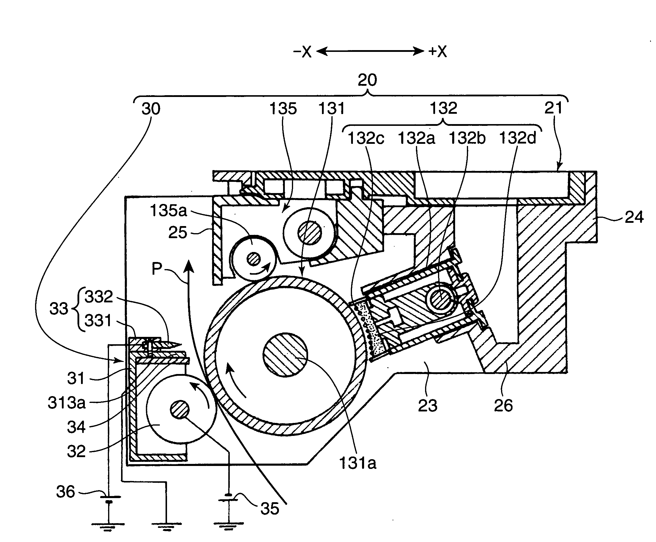
Thus, such an apparatus has a problem that the electric field formed by the charge-eliminating teeth does not always function properly to separate the toner image form the photosensitive drum peripheral surface, and the electric field does not show a desirable action because of leakage to the transfer member or the photosensitive drum.
Further, the apparatus disclosed in D3, in which a barrier of an insulating material is merely placed between the charge-eliminating teeth and the transfer member, does not give an advantageous effect as much as expected.

Method used


Image

  • Image forming apparatus
  • Image forming apparatus
  • Image forming apparatus

Examples


Embodiment Construction

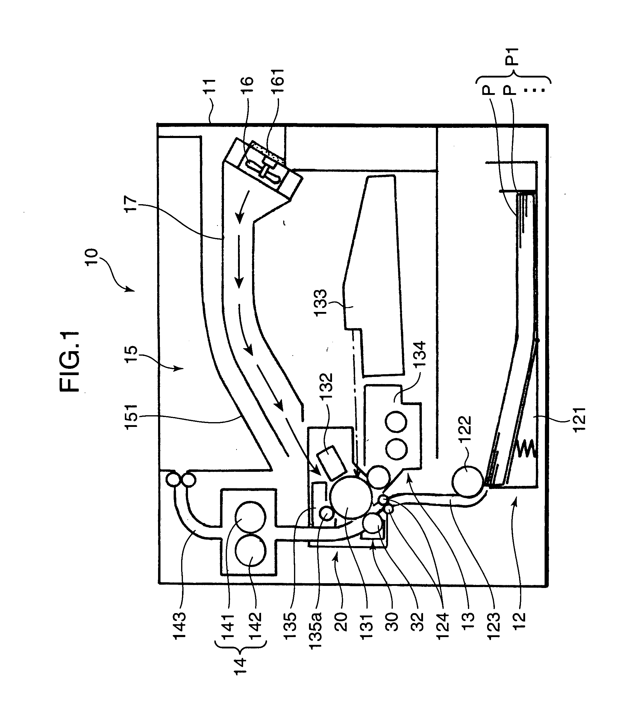
[0023]First, a printer, an example of the image forming apparatus according to the invention, will be described with reference to FIG. 1. FIG. 1 is a schematic front sectional view illustrating the internal structure of the printer in an embodiment. As shown in this Figure, the printer 10 has a sheet container 12 storing the transfer sheet P for use in printing, an image forming unit 13 transferring an image on each transfer sheet P fed from the transfer sheet bundle P1 stored in the sheet container 12, a fixing unit 14 fixing the transfer sheet P carrying the image transferred in the image forming unit 13, all of which are provided inside an apparatus housing 11, and a sheet discharge unit 15 to which the transfer sheet P fixed in the fixing unit 14 is discharged that is provided on the top of the apparatus housing 11.

[0024]A certain number (one in this embodiment) of sheet cassettes 121 are removably placed in the sheet container 12 inside the apparatus housing 11. There is a pick...


PUM


Abstract

An image forming apparatus comprises: a revolving image bearing member on which a toner image is formed; a transfer member that is provided at a position facing the surface of the image bearing member and transferring the toner image electrostatically on a transfer sheet traveling between the image bearing member and the transfer member; a static charge eliminator generating an electric field for discharging the electric charge on the transfer sheet for separation of the transfer sheet carrying the transferred toner image from the image bearing member; and a conductive member that is provided between the static charge eliminator and the transfer member.

Description

BACKGROUND OF THE INVENTION[0001]1. Field of the Invention[0002]The present invention relates to an image forming apparatus transferring a toner image on a transfer sheet, and in particular, to improvement of an electrostatic charge eliminator for discharge of the transfer sheet after transfer.[0003]2. Description of the Related Art[0004]Image forming apparatuses normally have a basic configuration consisting of a photosensitive drum (image bearing member) driven to rotate around its shaft center, and an electrostatic charger, an exposure device, a developing device, a transfer member and a cleaning device provided around it.[0005]The photosensitive drum is driven to revolve around its shaft center, and the peripheral surface of the photosensitive drum is charged uniformly by application of high voltage from the electrostatic charger. An electrostatic latent image is then formed on the peripheral surface by irradiation of the light emitted from the exposure device, based on the imag...

Claims


Application Information

Patent Timeline
Patent Type & Authority Applications(United States)
IPC IPC(8): G03G15/18
CPCG03G15/657G03G2215/00573G03G2215/004
Inventor TAKAGAMI, AI
Owner KYOCERA DOCUMENT SOLUTIONS INC
Learn More