Dual Band Antenna Feeding

a dual-band antenna and feeding technology, applied in the direction of polarised antenna unit combinations, resonant antennas, antenna earthings, etc., can solve the problems of difficult and time-consuming replacement, tedious and labor-intensive mounting of a bunch of cables, and the use of several different cables, so as to facilitate mounting and facilitate mounting. , the effect of eliminating laborious assembling steps

Inactive Publication Date: 2008-01-31
INTEL CORP +1
View PDF5 Cites 26 Cited by
  • Summary
  • Abstract
  • Description
  • Claims
  • Application Information

AI Technical Summary

Benefits of technology

[0008] An object of the present invention is to provide an antenna construction that overcomes the above mentioned disadvantages. In particular, it is an object of the invention to provide separate feedings in a dual band antenna giving desired radiation patterns in an easily mountable way. In accordance with the invention, the mounting is facilitated, whereby laborious assembling steps are eliminated, and thereby giving a less expensive dual band antenna. Further, a dual band antenna is provided having reliable and secure feeding of the radiating elements of a dual band antenna, giving desired radiation patterns. Further yet, the invention provides a new, inventive and simpler separate feeding of two or more antenna elements in a dual band antenna.

Problems solved by technology

There are a number of drawbacks with the prior art solutions.
Firstly, the solution presented in EP 1 069 646 A2 entails a tedious and labour intensive mounting of a bunch of cables, one for each patch being used.
Therefore the mounting is rendered even more difficult.
Further yet, the use of several different cables also gives a difficult and time consuming replacement, should a cable prove to be defect, or break down.

Method used


Image

  • Dual Band Antenna Feeding
  • Dual Band Antenna Feeding
  • Dual Band Antenna Feeding

Examples


Embodiment Construction

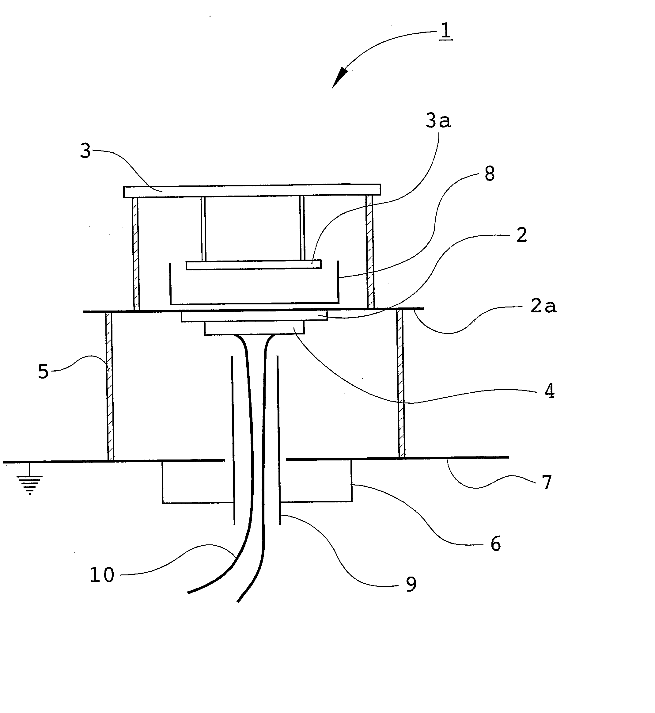
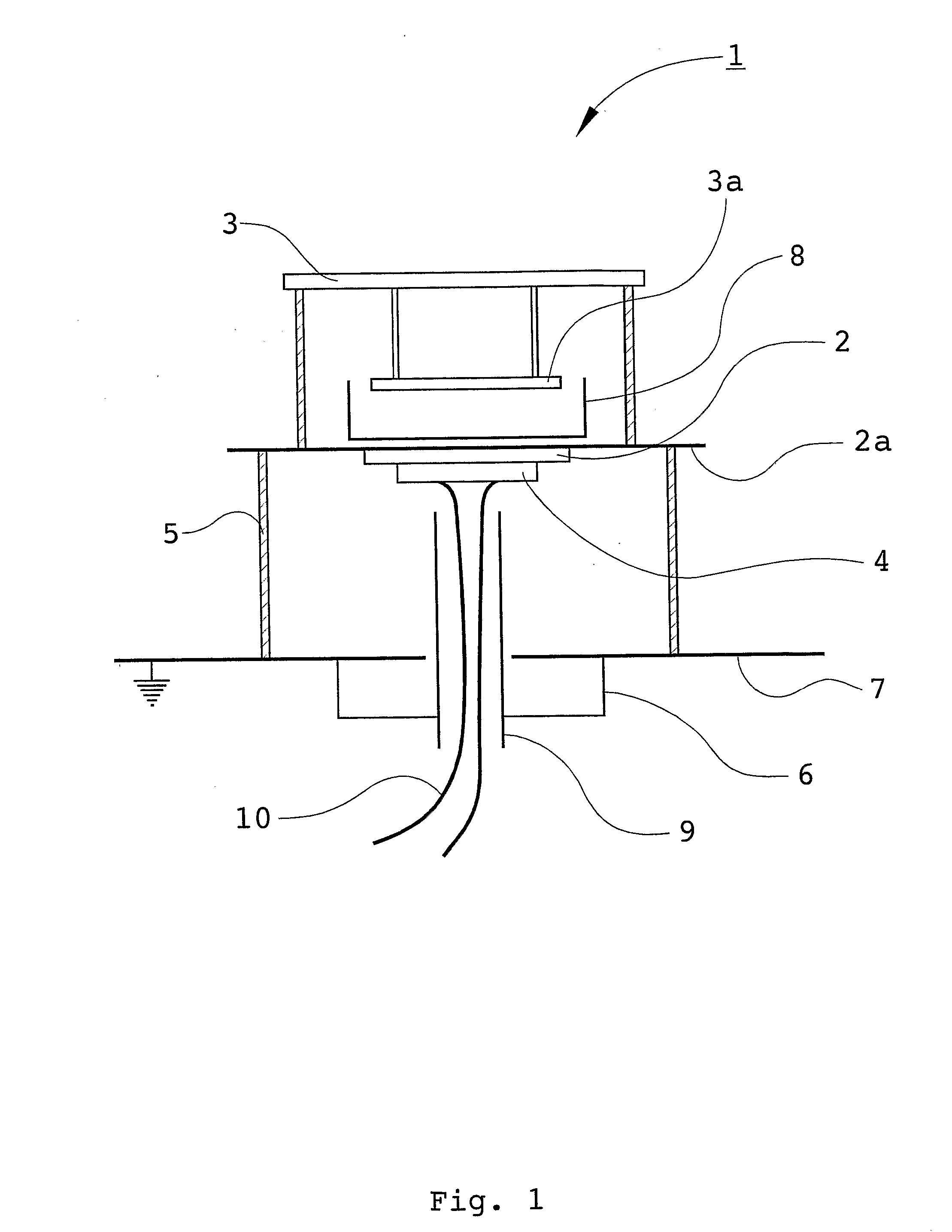
[0028] With reference first to FIG. 1, a schematic view of the dual band antenna in accordance with the present invention is shown. A dual band antenna 1 is generally indicated by reference numeral 1. A first antenna element 2 is provided, including radiating elements 2a, such as patches, made of an electrically conducting material for radiating at some frequency. The antenna element 2 is placed, for example by means of distances 5, above a primary reflector 7, whereby the reflector 7 is arranged to reflect radiation from the first antenna element 2. A shielding cage 6 is preferably also provided for preventing back radiation. A second antenna element 3, including radiating elements 3a, is placed above the first antenna element 2, and a secondary reflector 8 is provided for radiating radiation from the second antenna element 3.

[0029] The present invention is, in its most general form, based on the idea of using a shielded feeding means 9 through a first antenna element 2 to another...


PUM


Abstract

The present invention is related to a dual band antenna 1 comprising a number of antenna elements for transmitting and / or receiving radio frequency radiation. The antenna elements are placed above each other, and a shielded feeding means 9 is provided through a first antenna element 2 to a second antenna element 3 for separately feeding the different antenna elements 2, 3.

Description

[0001] This is a national stage of PCT / SE2005 / 001535 filed 14 Oct. 2005 and published in English.FIELD OF THE INVENTION [0002] The present invention is related to dual band antennas, of the kind apparent from the preamble of the attached claim 1. BACKGROUND OF THE INVENTION [0003] A typical dual band antenna comprises at least one first antenna element including a number of radiating patches, and an associated second antenna element for transmitting and / or receiving radio frequency radiation, and an electrically conductive, substantially planar reflector device. The first and second antenna elements form a combined antenna element on a front side of the reflector device. Microwave power is typically fed from a single feeding network in two separate frequency bands. The microwave power in a first frequency band is being fed via an aperture in the reflector device to a first radiating patch, and the microwave power in a second frequency band is being fed via the aperture in the reflec...

Claims


Application Information

Patent Timeline
Patent Type & Authority Applications(United States)
IPC IPC(8): H01Q9/04H01Q1/52H01QH01Q1/48H01Q5/00H01Q9/36
CPCH01Q1/526H01Q9/0414H01Q5/40H01Q9/0457H01Q21/26H01Q9/0428
Inventor UDDIN, JESPERLINDMARK, BJORNNORDSTROM, ANDREAS
Owner INTEL CORP
Why Eureka
Try Eureka