System and method for geometric apodization

a geometric apodization and geometric apodization technology, applied in the field of digital signal processing, can solve the problems of affecting image analysis, sidelobes having a tendency to raise the noise floor in an image, and the removal of sidelobes from sampled images is a common problem, so as to achieve the effect of suppressing the sidelobe structur

Inactive Publication Date: 2008-01-31
HARRIS CORP
View PDF1 Cites 10 Cited by
  • Summary
  • Abstract
  • Description
  • Claims
  • Application Information

AI Technical Summary

Benefits of technology

[0006]Briefly, according to an embodiment of the invention, a complex image is apodized to suppress sidelobes. An original complex image of an object is received. The complex image comprises a plurality of data points and sidelobes. The complex image is transformed to a k-space image which is then trimmed to remove all points outside of a geometric shape. This trimming is done with the shape overlaying the image and being at a first angle with respect to the image. The trimming prod

Problems solved by technology

The removal of sidelobes from sampled images is a common problem in image processing.
Sidelobes in an image hinder an image analyst's ability to detect weak targets or see dim sections of an image.
Sidelobes have a tendency to raise the noise floor in an image.
This in turn has a tendency to obscure dim objects in a scene.
However, when data is rigorously processed in the full 3D volumetric counterpart, there are sidelobes in all dimensions.
There are many sidelobe removal techniques but they all have different limitations or different side effects.
Windowing is a well-known method for reducing sidelobes, but it has the drawback of increasing the width of the mainlobe, which reduces image resolution.
Spatially Variant Apodization is a well-known method for reducing sidelobes, but it has the drawback of requiring specific collection criteria and / or re-sampling of the original data if it does not meet these criteria.

Method used


Image

  • System and method for geometric apodization
  • System and method for geometric apodization
  • System and method for geometric apodization

Examples


Embodiment Construction

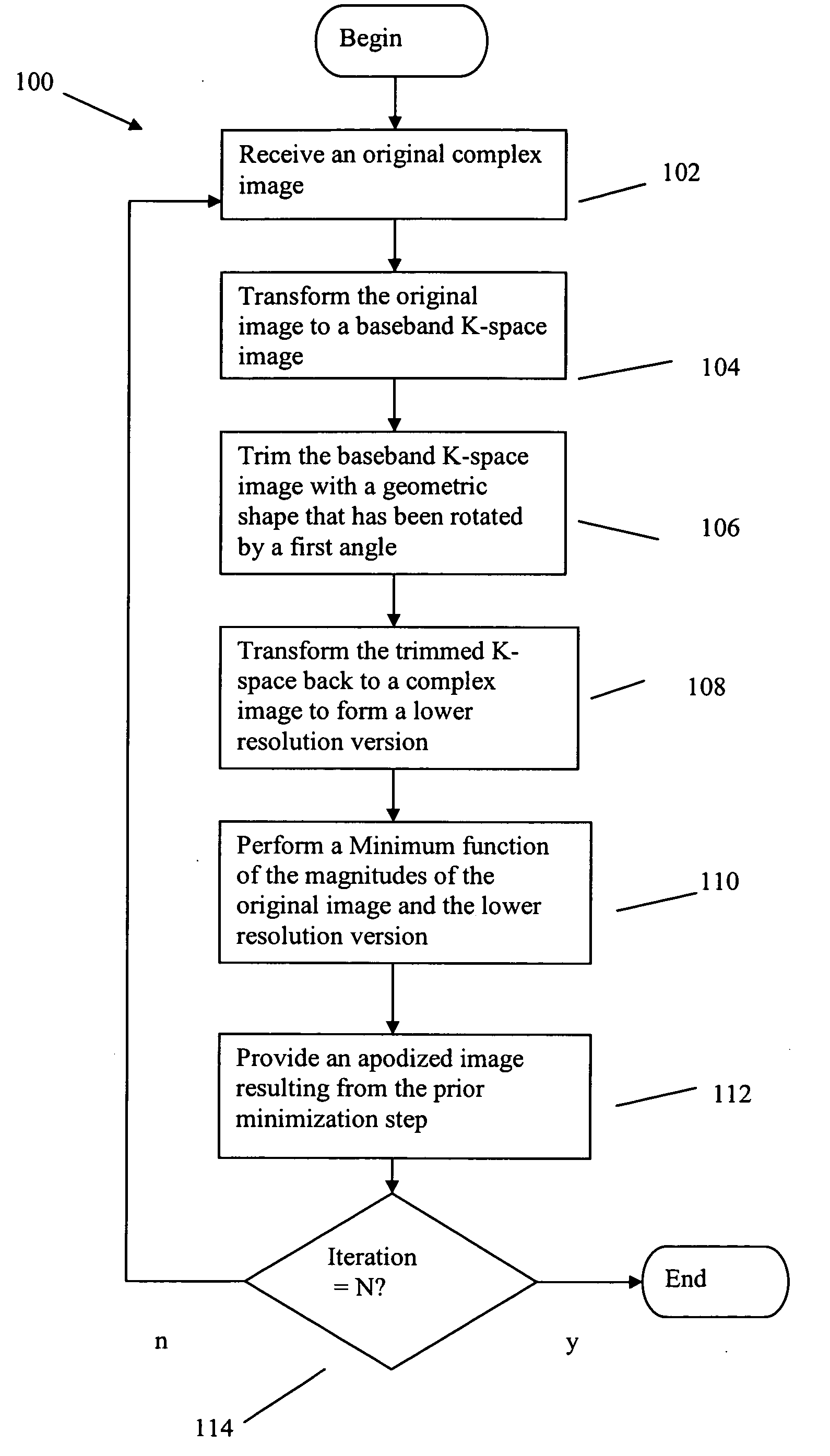
[0026]The above problems are solved by a method and system called geometric-based apodization (GBA) which uses the concept of trimming k-space data with a varying trim shapes (i.e., geometry), varying sizes of the trim shapes, and varying orientation of the trim structure (i.e., rotation), as well as varying translated positions of the “trim” in k-space, to control the direction of the sidelobes. In the embodiment discussed herein the trimming utilized is square trimming but other shapes can also be used. In this embodiment square shape is used to remove all points outside the square.

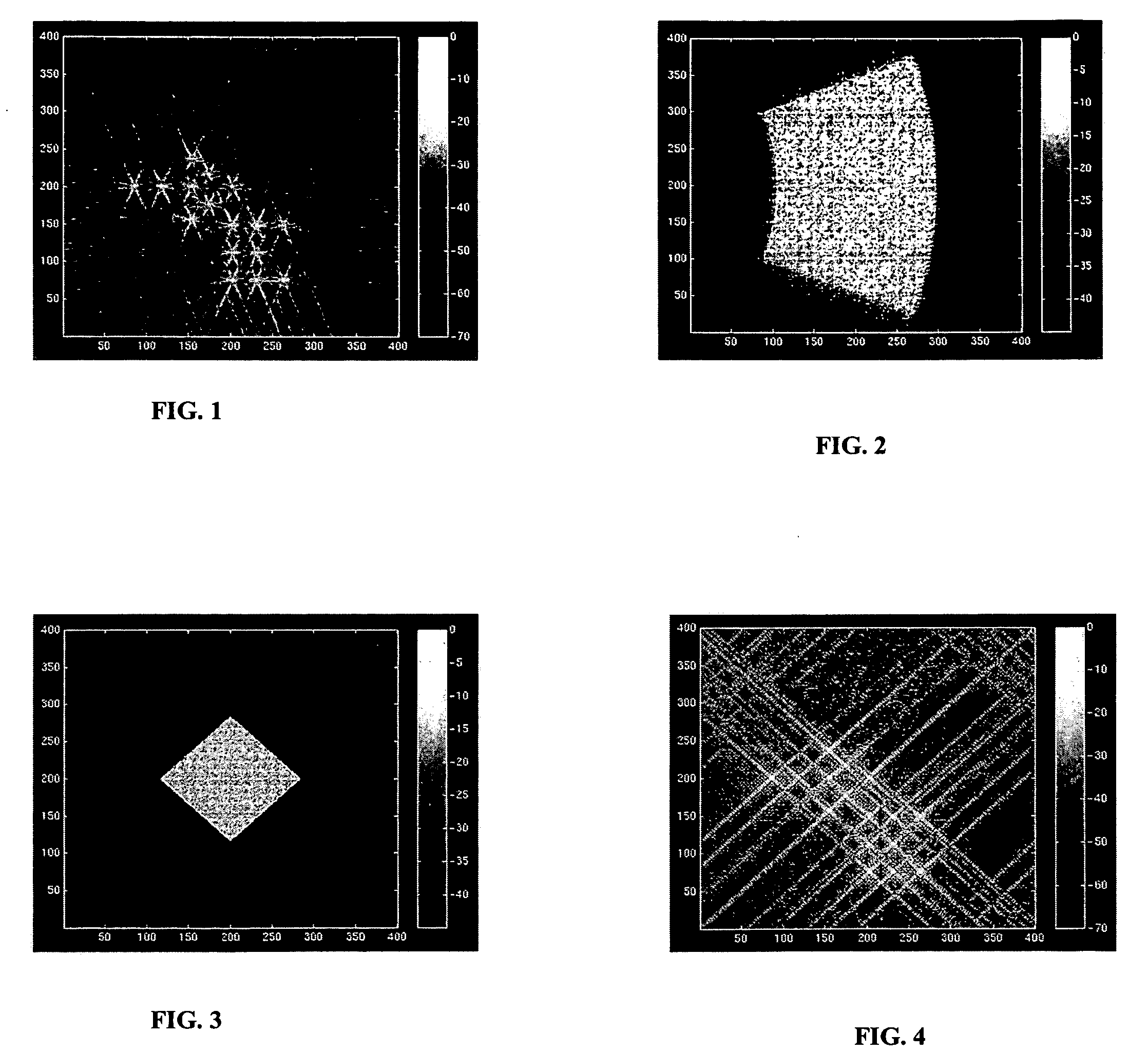
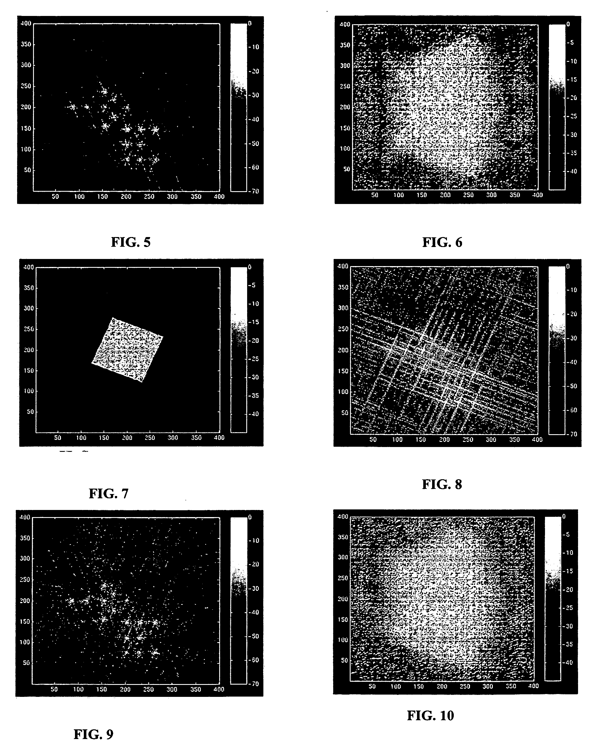
[0027]The embodiment now discussed is a method operating on a synthesized set of point targets. This original image is approximately 0.6 meter resolution in range and azimuth in the native slant plane. The example image is a SAR (Synthetic Aperture Radar) image formed from broadside beam dragging from short range utilizing 40 degree beamwidth. The data is rendered at 0.5 meter pixel spacing in the ENU (...


PUM


Abstract

A complex image is apodized to suppress sidelobes. An original complex image of an object is received. The complex image comprises a plurality of data points and sidelobes. The complex image is transformed to a k-space image which is then trimmed to remove all points outside of a geometric shape. This trimming is done with the shape overlaying the image and being at a first angle with respect to the image. The trimming produces a trimmed k-space image. The trimmed k-space image is then converted back to a new complex image having a sidelobe structure different from the original complex image. The new complex image is then normalized by adjusting its intensity such that its peak amplitude matches a peak amplitude in the original complex image. A minimum function is then performed on the magnitudes of the original and new complex images. The result is an apodized image with suppressed sidelobe structure.

Description

FIELD OF THE INVENTION[0001]The invention disclosed broadly relates to the field of digital signal processing, and more particularly relates to the field of removal of sidelobes.BACKGROUND OF THE INVENTION[0002]The removal of sidelobes from sampled images is a common problem in image processing. Sidelobes are an artifact of limited bandwidth. Basically the sidelobe structure is created by the particulars of the collection of the data. Sidelobes are commonly seen as a starburst affect on each scatterer in an image. Sidelobes in an image hinder an image analyst's ability to detect weak targets or see dim sections of an image.[0003]Sidelobes have a tendency to raise the noise floor in an image. This in turn has a tendency to obscure dim objects in a scene. Dim objects that are in proximity of bright objects are particularly affected. Although sidelobes are not part of the real scene, sidelobes are actually present in the raw data representing the scene. Therefore any removal of sidelob...

Claims


Application Information

Patent Timeline
IPC IPC(8): G01S13/90
CPCG01S13/9035G01S13/89G01S13/9004
Inventor WATKINS, WILLIAM W.GANTHIER, EMILEHENDRICKSON, KENNETH J.
Owner HARRIS CORP
Why Eureka
Try Eureka