
Dryer

a dryer and drying machine technology, applied in drying machines, lighting and heating apparatus, furnaces, etc., can solve the problems of large amount of steam generated by the dryer, rapid rise and stay of the inner part of the dryer, and condensation of steam on the inner wall, so as to reduce the required power and prevent the polluting of the environment by poisonous air

Inactive Publication Date: 2008-01-31
LEE SHING HONG
View PDF3 Cites 10 Cited by
  • Summary
  • Abstract
  • Description
  • Claims
  • Application Information

AI Technical Summary

Benefits of technology

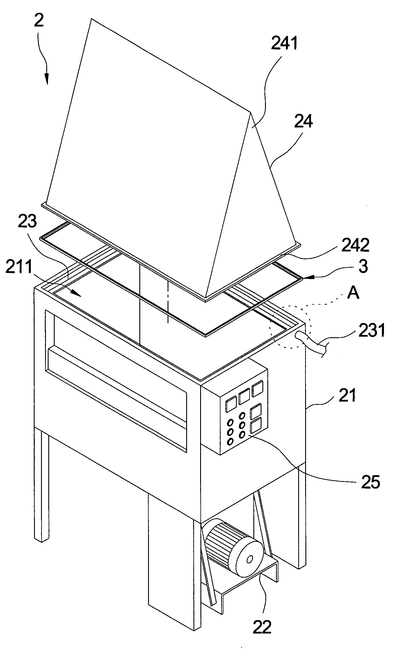
[0008]One particular aspect of the present invention is to provide a dryer. The dryer can exhaust water drops condensed on the inner wall to prevent the water drops from dropping onto dried objects, reduces required power, can be operated at a high temperature to achieve a disinfecting effect, and prevents poisonous air from polluting the environment.
[0010]The dryer includes a dryer body having an upward opening, a driving device connected with the dryer body, a control device connected with the dryer body, a groove located around the upward opening of the dryer body, an upper cover, and a heat insulating element. The upper cover has a cone shape. The angle of the cone end is larger than 0 degrees and is less than or equal to 35 degrees. The upper cover is located at the opening of the dryer body. The edge of the bottom of the upper cover is located at the groove. The heat insulating element is disposed in the groove and is disposed between the dryer body and the upper cover for preventing heat transmitted from the dryer body to the upper cover.
[0011]When the dryer is operating, steam rises and condenses to water drops on the inner wall of the upper cover. The angle of the upper cover makes the water drops slide downward along the inner wall of the upper cover as to prevent the water drops from dropping onto the dried objects. The groove is used for collecting the condensed water drops and preventing the water drops from dropping onto the dried objects when the water drops slide downward along the inner wall of the upper cover.

Problems solved by technology

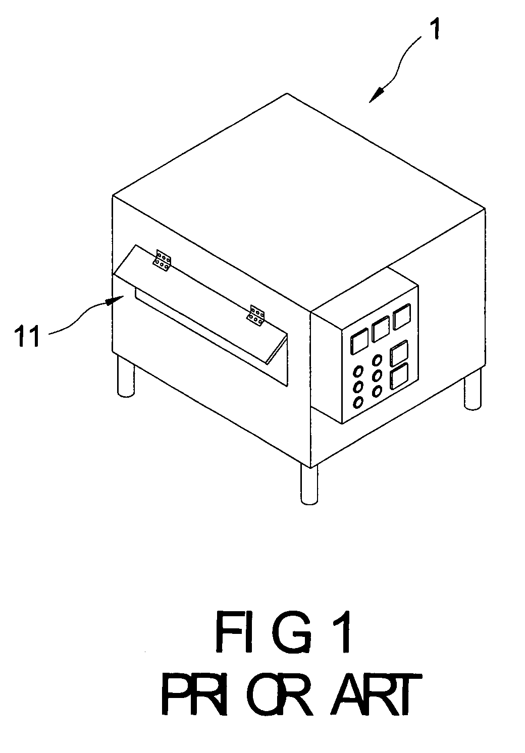
Therefore, the dryer generates large amounts of steam during the drying process.
Because the sealed space doesn't release heat easily, the temperature in the inner part of the dryer rises rapidly and stays high.
However, in the sealed space, when the steam contacts the inner wall of the dryer, the steam condenses on the inner wall and forms water drops.
Therefore, the drying time becomes longer and the power is wasted.
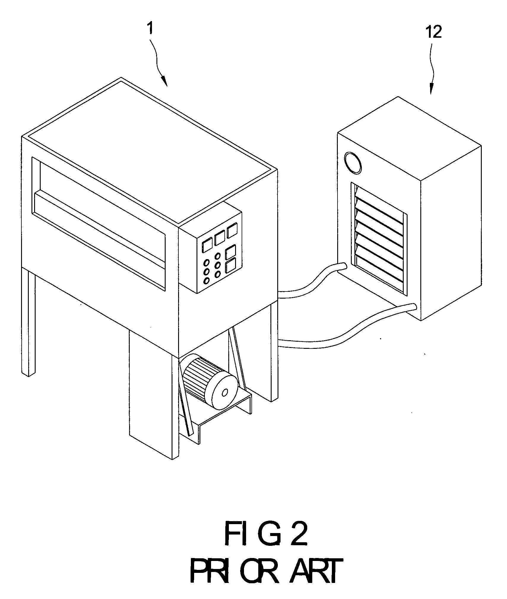
However, exhausting the high temperature steam makes drier air enter the dryer 1 and lower the temperature.
Therefore, because it takes time to increase the temperature in the dryer 1, power is wasted and the temperature in the dryer 1 cannot be maintained at a high temperature.
Furthermore, continuously exhausting the steam also exhausts the odor of the dried object.
Moreover, when the dried objects have a toxic or foul smell, the exhausted steam pollutes the environment.

Method used


Image

  • Dryer
  • Dryer
  • Dryer

Examples


Embodiment Construction

[0023]Reference is made to FIGS. 3˜4A. The dryer 2 includes a dryer body 21, a driving device 22, a groove 23, an upper cover 24, a control device 25, and a heat insulating element 3 disposed in the groove 23. The dryer body 21 has an upward opening 211. In the inner part of the dryer body 21, there is a heating device and a stirring device (not shown in the figure, the heating device and the stirring device are conventional devices). The driving device 22 is a motor, and is located under the dryer body 21 and is connected with the dryer body 21. The driving device 22 drives the stirring device to stir the object to make the object be dried uniformly. The control device 25 is used for turning on and turning off the driving device 22 and the heating device to control the dryer 2. The groove 23 is located around the opening 211 of the dryer body 21. An exhausting water pipe 231 is connected with the groove 23 for exhausting the water collected in the groove 23. The upper cover 24 is m...


PUM


Abstract

A dryer includes a dryer body, a driving device, a groove, and an upper cover. The groove is located around the opening of the dryer body. The upper cover has a cone shape and is located at the opening of the dryer body. The edge of the bottom of the upper cover is located at the groove. The angle of the cone end of the upper cover makes the water drops condensed on the inner wall of the upper cover slide downward along the inner wall of the upper cover so that they are collected in the groove.

Description

CROSS REFERENCE TO RELATED APPLICATION[0001]This application is a continuation-in-part of U.S. application Ser. No. 11 / 494,906, filed on 31 Jul. 2006 and entitled “A DRYER”, now pending.BACKGROUND OF THE INVENTION[0002]1. Field of the Invention[0003]The present invention relates to a dryer. In particular, this invention relates to a dryer that prevents drops of condensed water that form on the inner wall of the dryer from dropping onto the dried objects in the dryer.[0004]2. Description of the Related Art[0005]Dryers are used for vaporizing water in the object that is placed in the dryer. Therefore, the dryer generates large amounts of steam during the drying process.[0006]Generally, the more sealed the space is, the faster the drying speed is. Because the sealed space doesn't release heat easily, the temperature in the inner part of the dryer rises rapidly and stays high. However, in the sealed space, when the steam contacts the inner wall of the dryer, the steam condenses on the i...

Claims


Application Information

Patent Timeline
IPC IPC(8): F26B3/00
CPCF26B7/00F26B25/006F26B11/02
Inventor LEE, SHING-HONG
Owner LEE SHING HONG
Learn More