
Exercise device with centrally mounted resistance rod

a technology of resistance rod and exercise device, which is applied in the direction of resilient force resistors, gymnastic exercise, and machines that are heavy, and can solve the awkward manner in which the hook apparatus must be used to bundle the flexible rods together, and achieve the effect of convenient device storag

Inactive Publication Date: 2008-01-24
ICON IP
View PDF99 Cites 22 Cited by
  • Summary
  • Abstract
  • Description
  • Claims
  • Application Information

AI Technical Summary

Benefits of technology

"The present invention is an exercise machine that uses a support assembly, resilient elongate members, a cable and pulley system, and a bench for user exercise. The machine allows users to exercise against the resistance provided by the flexible elongate members, with adjustable resistance using capture devices. The cable and pulley system provides compounding effects of resistance, and the machine has additional features such as a plurality of elongate members positioned on a fulcrum, a capture device enabling one handed addition or removal of resistance rods, movement of both ends of the elongate members when the cable is drawn, and a plurality of additional features and benefits. The machine also includes a bench for balance and stability and a leg exercise unit attached to the bench for a variety of leg exercises. The technical effects of the invention include improved resistance training, flexibility, and a wide range of exercise options."

Problems solved by technology

However, due to the mass of the weights, these machines are heavy and can be difficult for a home user to move.
However, the manner in which the hook apparatus must be used to bundle the flexible rods together is awkward, requiring the use of two hands, i.e. a first hand to hold the hook and a second hand to thread the hook through the loops on the rods.
In addition, since there are two sets of rods, there are two independent sources of resistance, adding a level of complexity to the use of the exercise apparatus.
Moreover, the length of the user's stroke is limited to the how far the ends of the flexible rods can be displaced, whereas certain exercises require a long stroke.

Method used


Image

  • Exercise device with centrally mounted resistance rod
  • Exercise device with centrally mounted resistance rod
  • Exercise device with centrally mounted resistance rod

Examples


Embodiment Construction

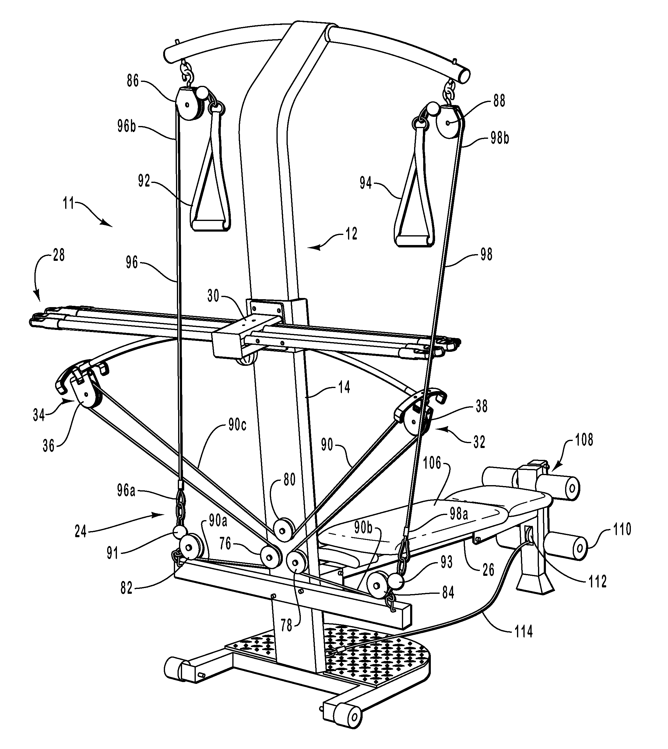
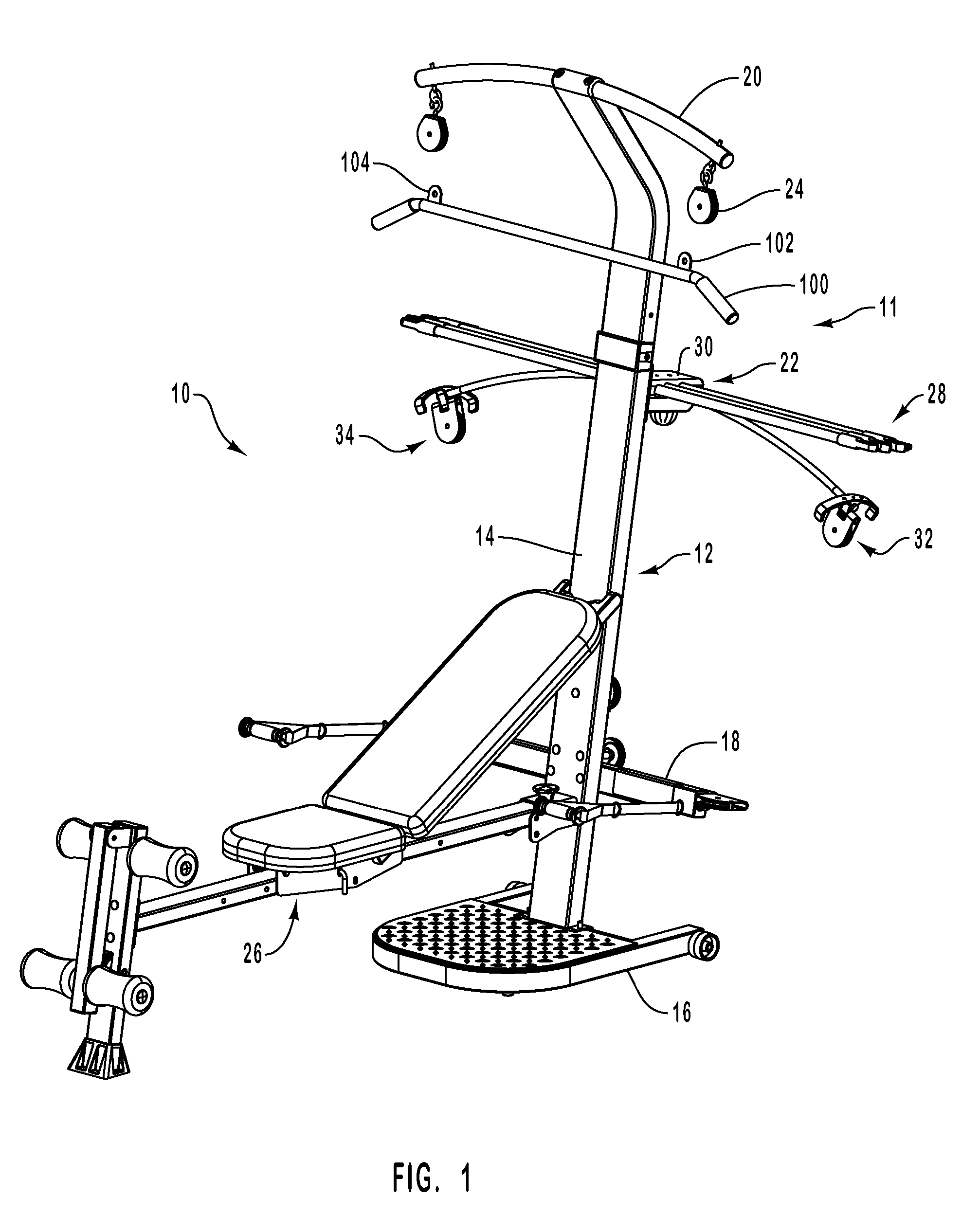
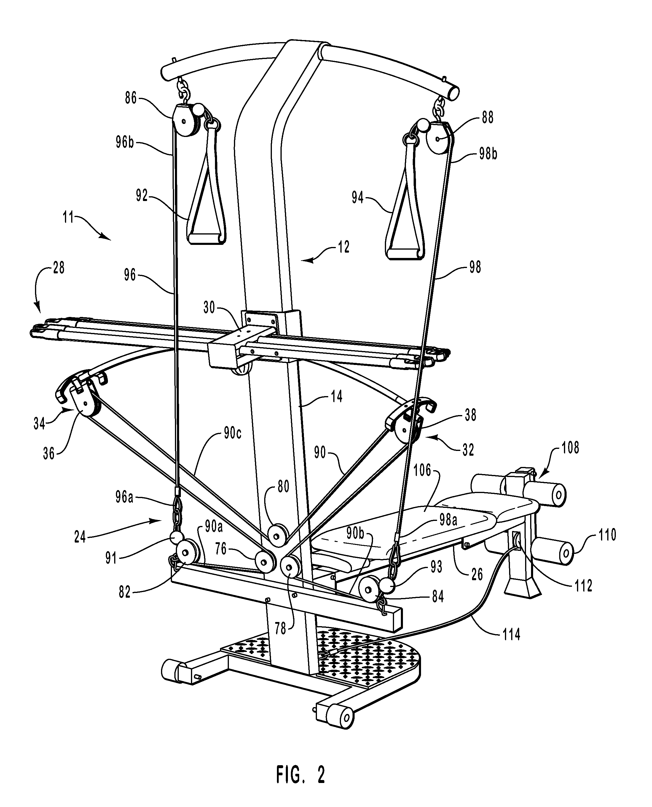
[0031] An exercise machine 10 of the present invention is shown in FIG. 1. Exercise machine 10 of FIG. 1 includes a support assembly 11 comprising (i) a frame 12 and (ii) a fulcrum 30. Support assembly 11 provides a mechanism for integrating components of the exercise machine 10, the components including, for example, a plurality of resilient elongate members 28, a cable and pulley system 24 (cables not shown in FIG. 1), and, optionally, a bench 26.

[0032] Frame 12 comprises a post 14, a base member 16 which contacts a support surface (e.g., a floor or the ground), a lower horizontal member 18 and an upper horizontal member 20. Post 14 provides a rigid upright for connecting various components of the present invention. Base member 16 is coupled to the bottom end of post 14 and may include wheels thereon for convenient moving of device 10. Base member 16 provides a bottom support for post 14.

[0033] Lower horizontal member 18 is coupled to post 14. Upper horizontal member 20 is coupl...


PUM


Abstract

An exercise machine has resilient elongate members for providing balanced resistance in the form of elongate resilient members oriented horizontally such that the intermediate portion of the elongate members contact a fulcrum of the exercise machine. The user adjusts the amount of resistance provided by capturing different combinations and members of resilient elongate members. A cable and pulley system ensures a long stroke so the user can perform a wide variety of exercises in comfortable positions.

Description

CROSS-REFERENCE TO RELATED APPLICATIONS [0001] This patent application is a continuation of U.S. patent application Ser. No. 10 / 173,515, filed Jun. 14, 2002 to Dalebout, et al, entitled “Exercise Device with Centrally Mounted Resistance Rod,” which is incorporated herein, in its entirety, by reference.BACKGROUND OF THE INVENTION [0002] 1. The Field of the Invention [0003] The present invention relates to exercise devices. More specifically, the present invention relates to an exercise device having resilient elongate members for providing resistance against which a user can exercise. [0004] 2. Background and Relevant Art [0005] Society in general is becoming more health-conscious. A result of this has been an increased demand for fitness devices that can be utilized to attain and maintain healthy levels of fitness. Multi-function exercise machines have been developed in response to this demand. Multi-function exercise machines are often adapted to be convenient to operate and store,...

Claims


Application Information

Patent Timeline
Patent Type & Authority Applications(United States)
IPC IPC(8): A63B21/04A63B21/02A63B21/045
CPCA63B21/045A63B21/026
Inventor DALEBOUT, WILLIAM T.OLSON, MICHAEL
Owner ICON IP
Learn More