
Vehicle Height Adjustment Device And Vehicle Height Adjustment Method

a technology of height adjustment device and vehicle, which is applied in the direction of loading/unloading vehicle arrangment, transportation items, wound springs, etc., can solve the problems of complex construction of height adjustment device, a number of manufacturing steps or manufacturing process, and the manufacture process of such a vehicle height adjustment device requires a number of manufacturing steps or manufacturing processes, so as to reduce the number of parts or members, the effect of simplifying the construction of the devi

Inactive Publication Date: 2008-01-24
ISUZU MOTORS LTD
View PDF16 Cites 87 Cited by
  • Summary
  • Abstract
  • Description
  • Claims
  • Application Information

AI Technical Summary

Benefits of technology

The present invention provides a vehicle height adjustment device for a vehicle suspension system that regulates the position of a spring seat member by using an adjustment bolt and a wheel-side member or a vehicle-body member. The device allows for easy adjustment of the vehicle height without the need for structural separation of the bolt from the wheel-side member or the vehicle-body member, which simplifies the construction of the device and reduces the number of parts. The position of the spring seat member is stabilized by a component of the wheel-side member or the vehicle-body member, and the rotation of the bolt is restricted without changing the position of the bolt in relation to the wheel-side member or the vehicle-body member. The device also includes a recess with an internal thread and a screw part engaging with the recess, as well as a rotating tool engagement means and a stabilized position of the spring seat member.

Problems solved by technology

However, a resilient repulsive force of a compression coil spring, which is not rotatable, normally acts on the spring seat.
Thus, a manufacturing process of such a vehicle height adjustment device requires a number of manufacturing steps or a complicated manufacturing process.
As a result, such a type of vehicle height adjustment device requires a complicated construction of the device and a number of parts or members for the device.

Method used


Image

  • Vehicle Height Adjustment Device And Vehicle Height Adjustment Method
  • Vehicle Height Adjustment Device And Vehicle Height Adjustment Method
  • Vehicle Height Adjustment Device And Vehicle Height Adjustment Method

Examples


Embodiment Construction

[0040] One preferred embodiment of the present invention is described in detail hereinafter, with reference to the accompanying drawings.

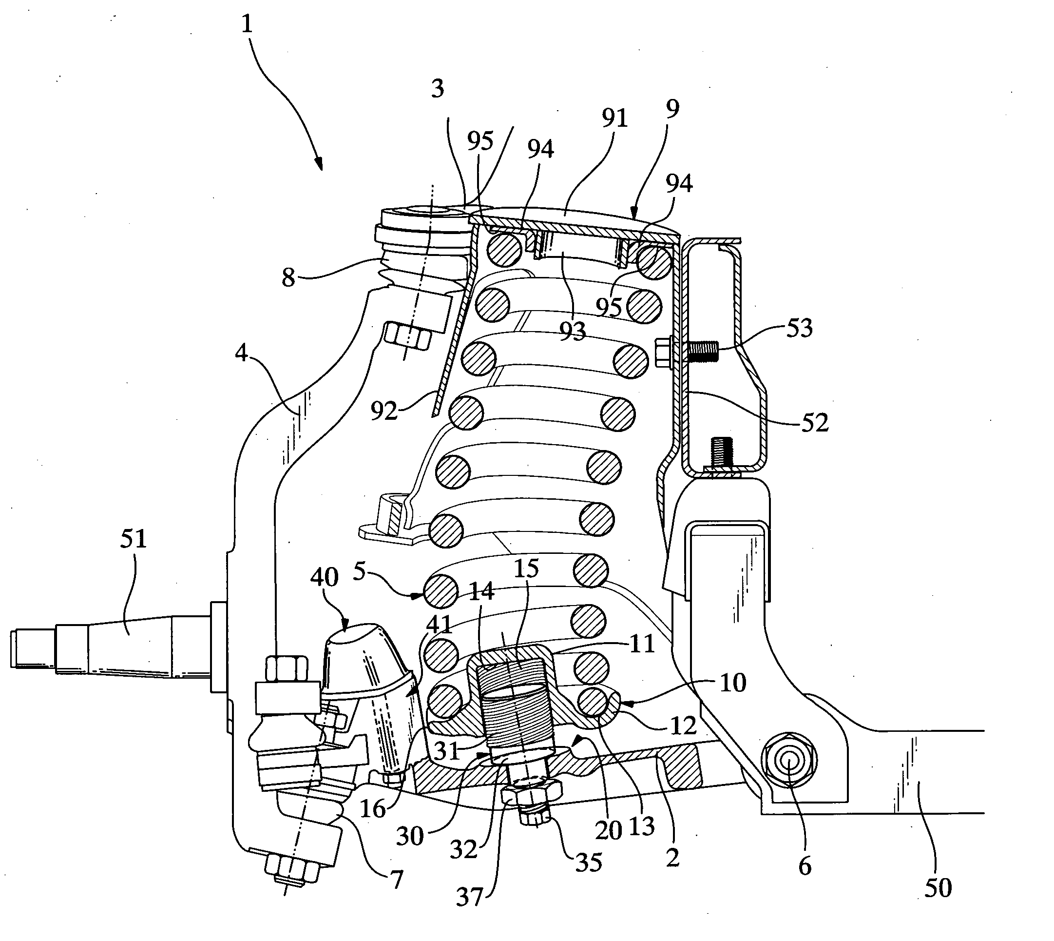
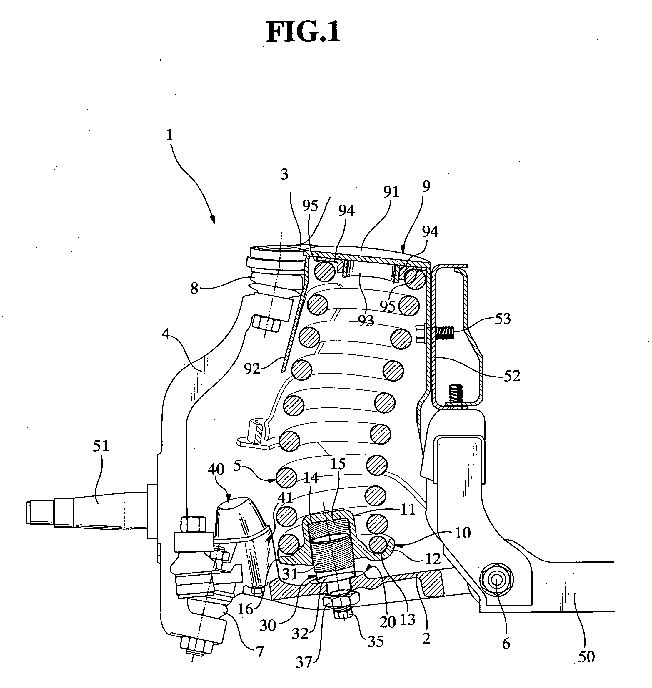
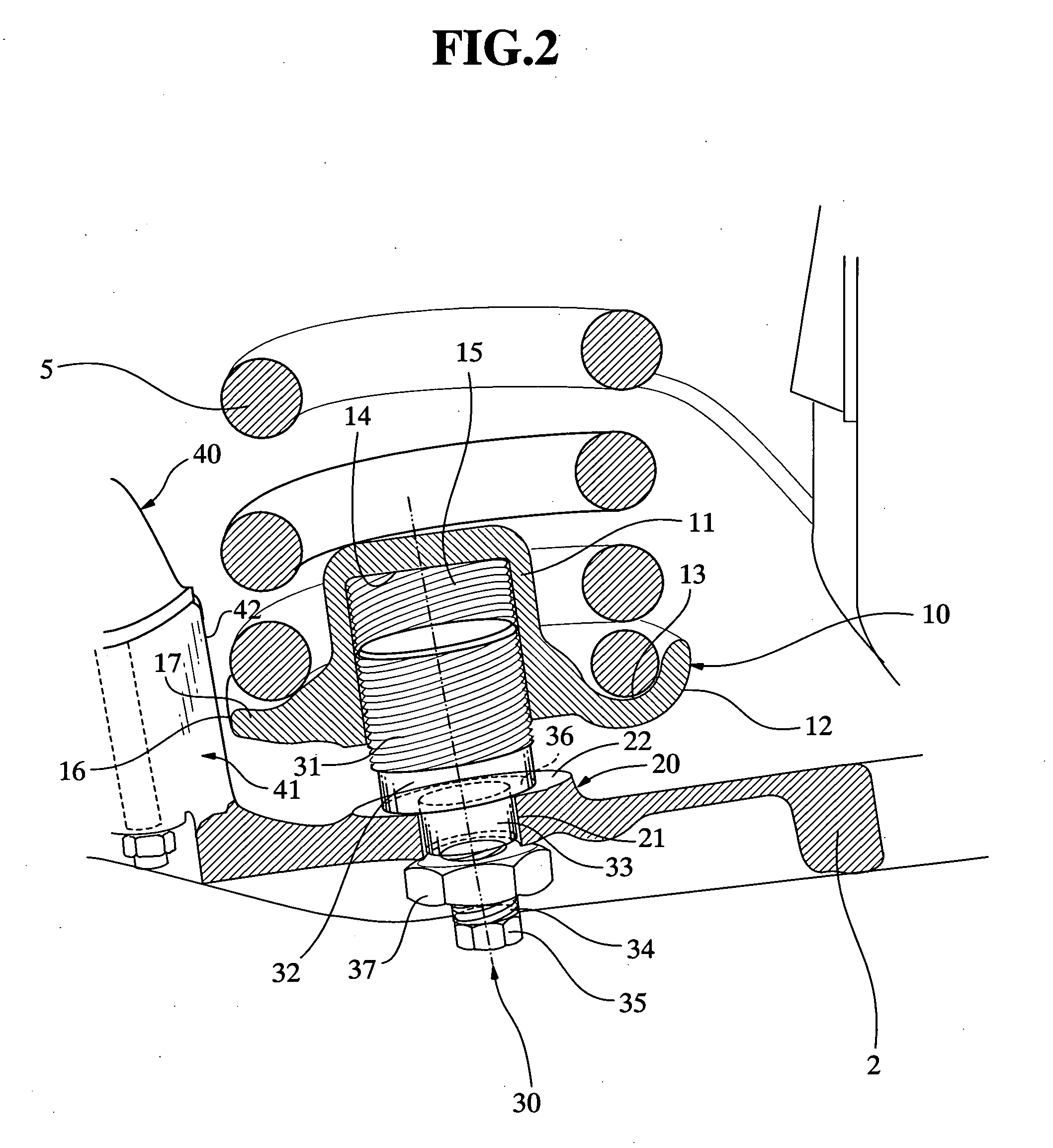
[0041]FIG. 1 is a partially cross-sectional side elevational view showing a construction of a main part of a vehicle suspension system provided with a vehicle height adjustment device according to the present invention, and FIGS. 2 and 3 are an enlarged cross-sectional view and an exploded cross-sectional view partially showing the device as shown in FIG. 1.

[0042] In FIG. 1, a main part of a double-wishbone-type suspension system (wheel suspension system) 1 is illustrated. The suspension system is provided with a lower arm 2, an upper arm 3, a knuckle 4 and a compression coil spring 5. One end portion of the lower arm 2 on a side of a vehicle body (an inner end portion) is swingably mounted on a vehicle-body member 50 by means of a pivot 6, whereas the other end portion of the lower arm 2 on a side of a wheel (an outer end portion) is articulated...


PUM


Abstract

A vehicle height adjustment device has an adjustment bolt (30) rotatably supported by or fixed to a wheel-side member or a vehicle-body member, and a spring seat member (10) threadedly engaging with the adjustment bolt. Rotation of the spring seat member is limited by a bump rubber pedestal (41) (or a coil spring bracket (9)). Displacement of the spring seat member occurs in an axial direction of rotation of the bolt, in accordance with rotation of the bolt. According to the present invention, rotation of the spring seat involved in rotation of the bolt for adjusting the vehicle height can be restricted, and a construction of a vehicle height adjustment mechanism can be simplified so that the number of parts or members of the device is reduced.

Description

TECHNICAL FIELD [0001] The present invention relates to vehicle height adjustment device and method for a suspension system, and more specifically, to such a device and method for adjusting the vehicle height by regulating a position of a spring seat member which abuts against an end portion of a compression coil spring interposed between a wheel-side member carrying a wheel and a vehicle-body member. TECHNICAL BACKGROUND [0002] A vehicle suspension system is known in the art, which has a compression coil spring interposed between a wheel-side member and a vehicle-body member, wherein upper and lower spring seats are provided for respectively supporting upper and lower end portions of the spring, and wherein a vehicle height adjustment device is equipped for adjusting the vehicle height by regulating a position of the spring seat. [0003] For example, Japanese patent publication No. 3,193,914 (JP 3,193,914 B) discloses a device for adjusting a vehicle height, which comprises a lower ...

Claims


Application Information

Patent Timeline
Patent Type & Authority Applications(United States)
IPC IPC(8): B60G17/00B60G11/16B60G17/02F16F1/12
CPCB60G11/16B60G17/021B60G2200/144F16F1/121B60G2204/61B60G2500/20B60G2500/30B60G2204/1244
Inventor HIRAO, SATOSHIKAWAHATA, SUSUMU
Owner ISUZU MOTORS LTD
Learn More