
Remoted controlled vehicle system

a remote control and vehicle technology, applied in the field of personal vehicles, can solve the problems of fewer hsp, careen out of control, crash, etc., and achieve the effects of saving lives, and reducing the speed of the vehicl

Inactive Publication Date: 2008-01-17
LUND ISAAC
View PDF7 Cites 35 Cited by
  • Summary
  • Abstract
  • Description
  • Claims
  • Application Information

AI Technical Summary

Benefits of technology

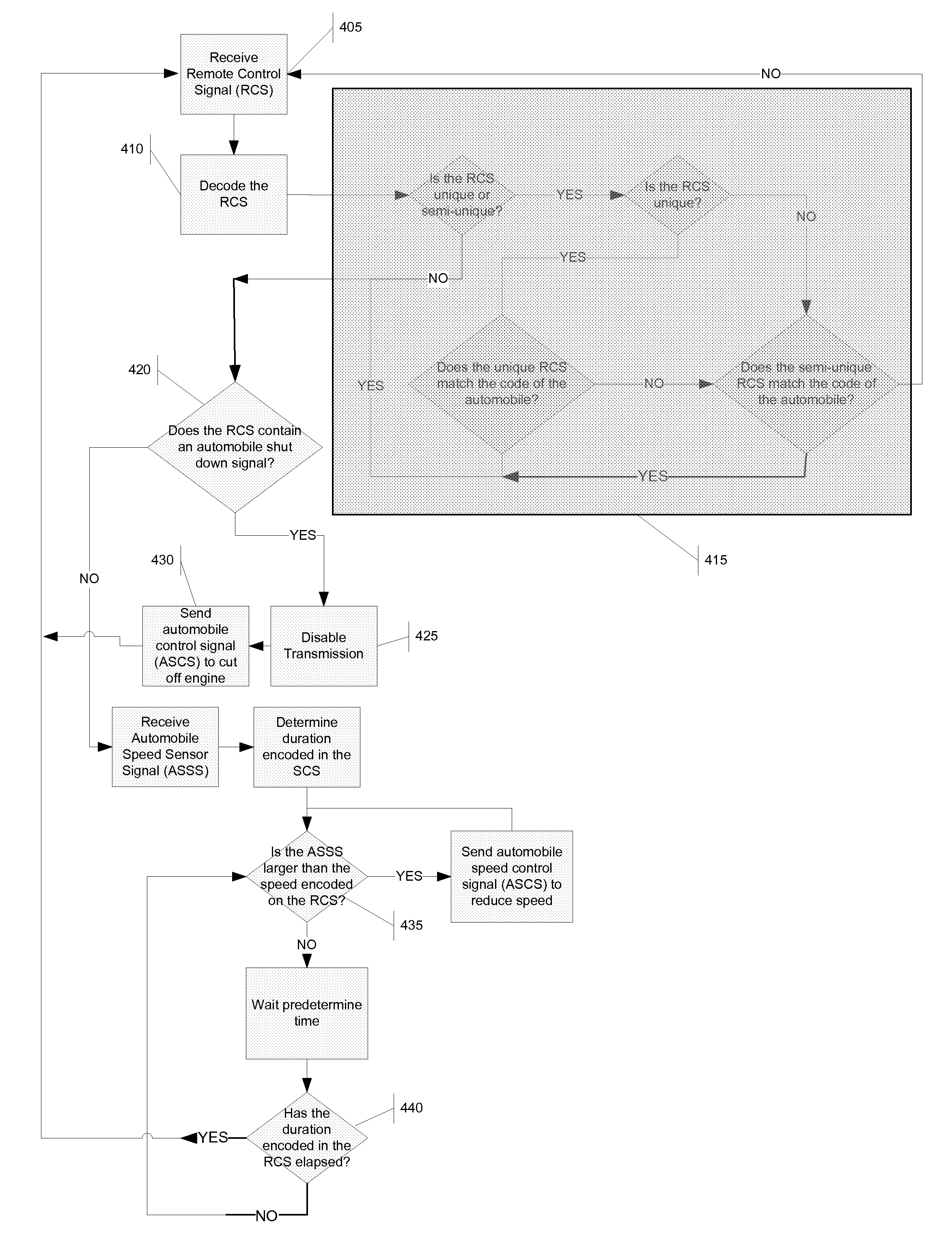
[0009]In one embodiment, the remote control signal may simply require that the vehicle slow down, which would be implemented by the CPU sending to the speed control device a signal to reduce the vehicle's speed. The CPU would constantly monitor its present speed (as determined by the speed sensor) against the speed encoded in the remote control signal until the encoded speed is attained. This embodiment may be useful in safety zones, such as construction areas and school zones, where reduced speeds can save lives.

Problems solved by technology

While the proposed legislation may reduce the number of HSP, it does not solve the root cause of the problem.
Ultimately, this may result in fewer HSP, while simultaneously rewarding criminals.
In bumping, the police officer may bump the backend of the evading vehicle causing it to careen out of control and crash.
Finally, a spike strip may be placed in front of the evading vehicle, causing its tires to blow out and making the vehicle much more difficult to control.
First, the pit maneuver requires several players placed in a precise formation.
This places several players in harm's way and it may not be feasible to execute one of these maneuvers in high-traffic areas.
Also, the evading vehicle may become more erratic attempting to evade being “boxed” in.
Bumping can be very dangerous to the occupants of the evading vehicle, the police officer executing the maneuver and any bystanders.
Also, bumping does not guarantee that the vehicle will be stopped.
Again, this may not be feasible in a high-traffic area.
Nor does the spike strip disable the vehicle from continuing to evade police.
In fact, the evading vehicle can continue the pursuit, but in a condition that makes it more erratic and less easily controlled.

Method used


Image

  • Remoted controlled vehicle system
  • Remoted controlled vehicle system
  • Remoted controlled vehicle system

Examples


Embodiment Construction

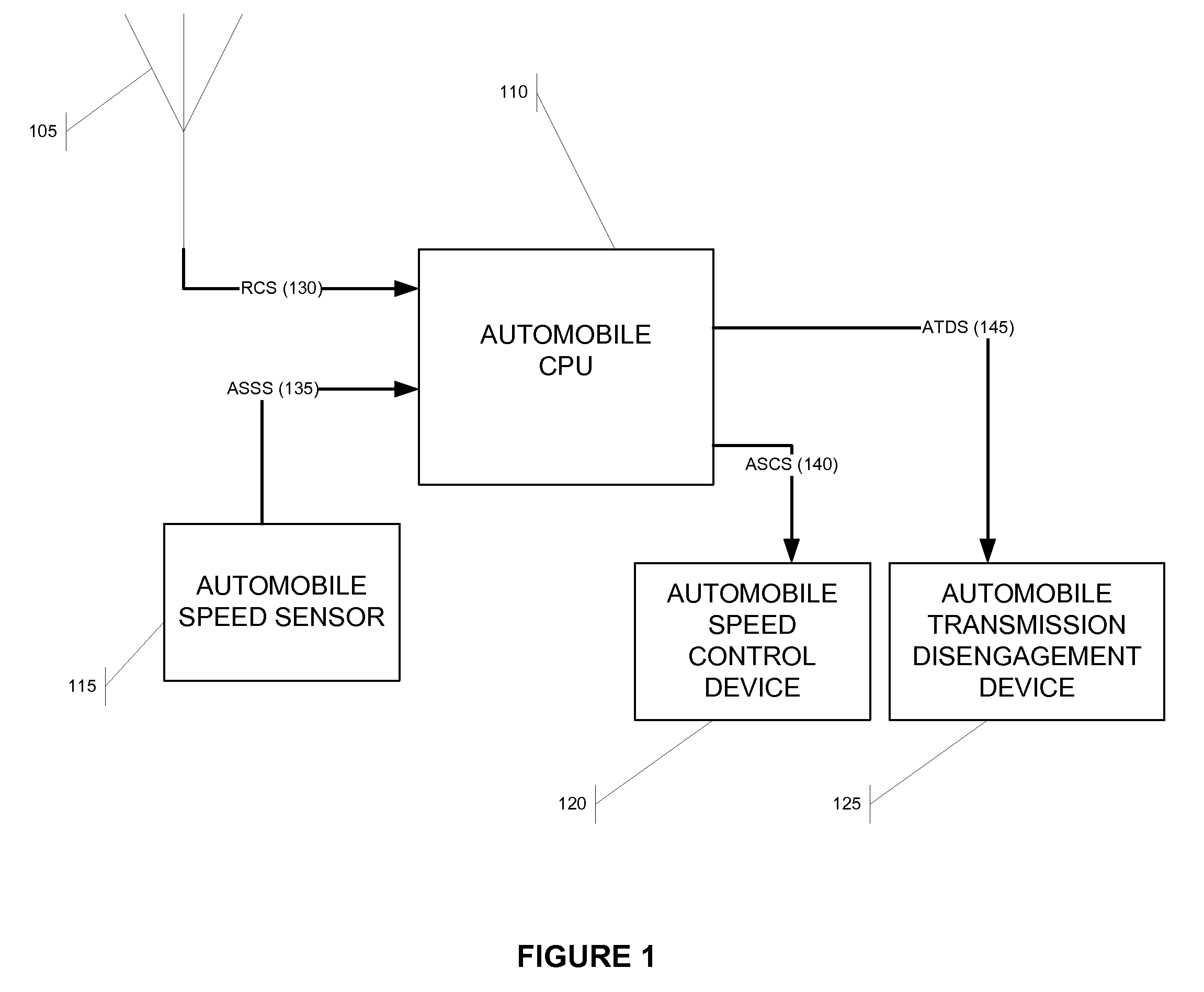
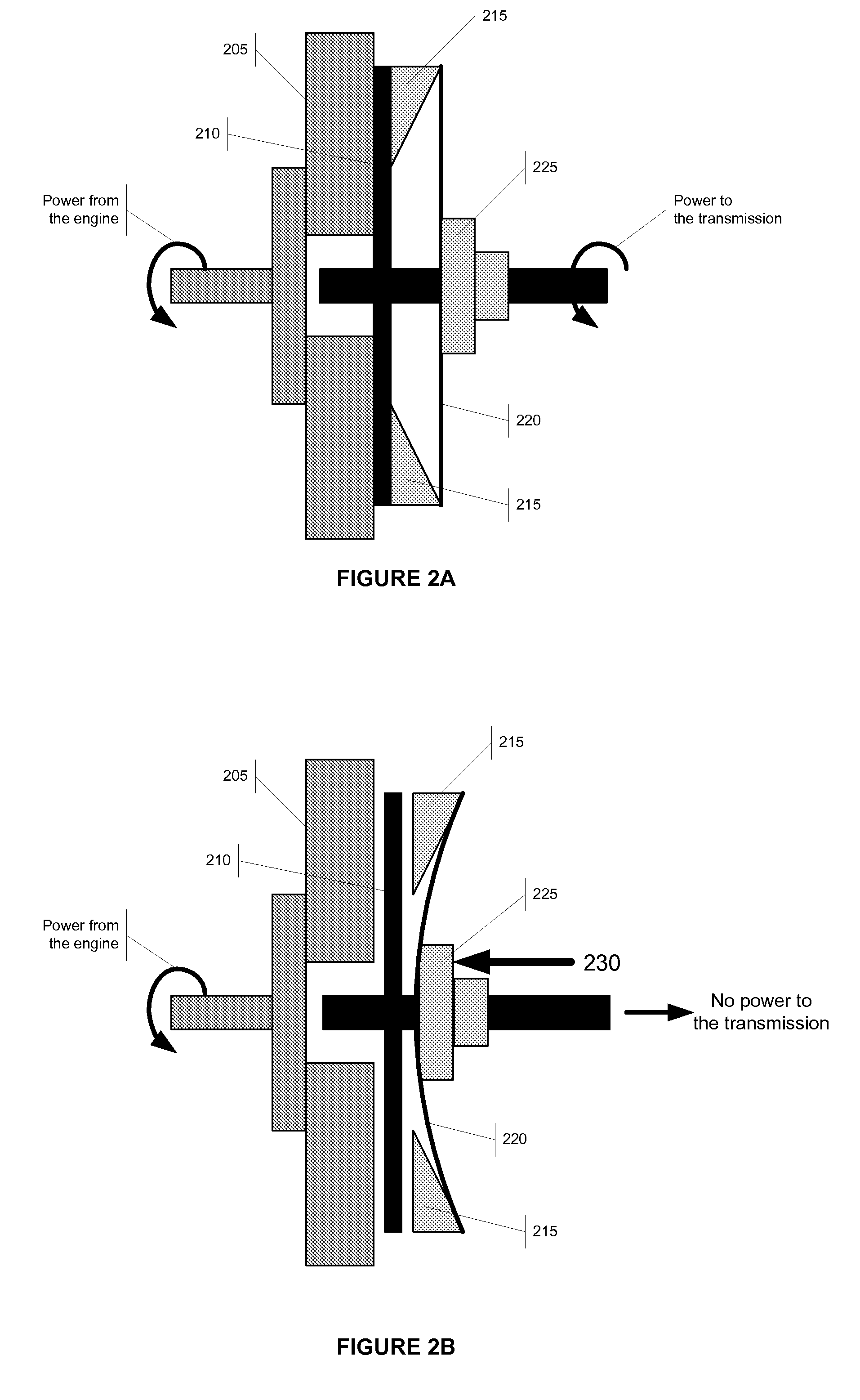
[0016]What is described below is a novel system that can slow or stop vehicles remotely. This system can be especially useful in HSP to bring an evading vehicle to a safe stop without endangering bystanders. FIG. 1 provides an overview of the system described herein. The system may comprise an antenna (105) a central processing unit (CPU) (110), an automobile speed sensor (115), an automobile speed control device (120) and, optionally, an automobile transmission disable device (125). The antenna (105) receives a wireless remote control signal (RCS) which it transmits to the CPU (110), as shown by control line 130. The RCS may include instructions to reduce speed and / or to stop the vehicle. It may also include the duration for which the reduction in speed should be sustained. The RCS is transmitted by a device external to the vehicle and is intended to commandeer a portion of the vehicle's control. For example, the transmitting device may be mobile (such as a police car or helicopter...


PUM


Abstract

A novel system and method for providing remote control of a vehicle is disclosed. The system comprises an antenna, a central processing unit, a speed sensor, a speed control device, and optionally, a transmission disengagement device. By sending a remote control signal to the vehicle, the vehicle can be slowed or completely stopped by cutting off power to the vehicle's drive train. The remote control signal can be keyed uniquely to a single vehicle or a small group of vehicles, such that only those vehicles in the group respond to the signal. The device and methods disclosed herein may be used in high speed pursuits to disable a vehicle and force it to a peaceful stop. The device and methods disclosed herein may also be used in safety zones such as construction areas or school zones to protect pedestrians.

Description

FIELD OF THE INVENTION[0001]The present invention relates to the personal vehicles, and more specifically, to the remote control of certain aspects of a personal vehicle.BACKGROUND OF THE INVENTION[0002]According to the National Highway Traffic Safety Administration, in 2003, California's 7,171 high-speed pursuits (HSP) caused 51 deaths, 18 of which were innocent bystanders. National statistics from 1982 to 2004 show that 7,430 deaths resulted from police HSP. While occupants of the chased vehicles accounted for most of those deaths, nearly 2,000 uninvolved motorists and bystanders also died.[0003]The epidemic of HSP has promptly several jurisdictions to propose new legislation aimed at curbing the incident of these pursuits. For example, under California's current law a police officer is immune from civil liability if that officer is involved in a HSP. California legislators have proposed legislation that removes the officer's immunity; thus, an officer could be held civilly liable...

Claims


Application Information

Patent Timeline
Patent Type & Authority Applications(United States)
IPC IPC(8): B60T8/32
CPCB60K31/0058B60R25/06G08G1/096766B60W10/02B60W10/06B60T7/22B60W2556/45
Inventor LUND, ISAAC
Owner LUND ISAAC
Learn More