
Printing apparatus and printing method for the same

a printing apparatus and printing method technology, applied in printing presses, typewriters, printing, etc., can solve problems such as troublesome adjustment work, error on vertical and horizontal dimensions, and many building boards with uneven design surfaces to be printed, and achieve good external wall design

Inactive Publication Date: 2008-01-17
NICHIHA CORP
View PDF3 Cites 2 Cited by
  • Summary
  • Abstract
  • Description
  • Claims
  • Application Information

AI Technical Summary

Benefits of technology

The present invention provides a printing apparatus and method for a building board that can create a smooth and continuous appearance when the boards are fastened to a building, even if there is a dimensional error. This results in a building board that looks good from the outside and is easy to install.

Problems solved by technology

In the cutting out process described above, an error on vertical and horizontal dimensions conceivably occurs due to nature of a hardened element of cement.
Therefore, a countermeasure is currently taken, in which the position where the building boards are fastened is adjusted vertically in an attempt to hide the deviation, though not sufficiently and the adjusting work is troublesome.
(2) Many of building boards have an uneven design surface to be printed.
However, although either of the methods described in the Japanese Patents above has a processing configuration of ink-jet, the same is not beyond the coating technology.
In other words, since the methods use a coating material that is previously toned, a full-color printed image cannot of course be expressed.
As described above, in the building board of the ceramic series (cement series), occurrence of a dimension error caused by a manufacturing method thereof cannot be avoided.
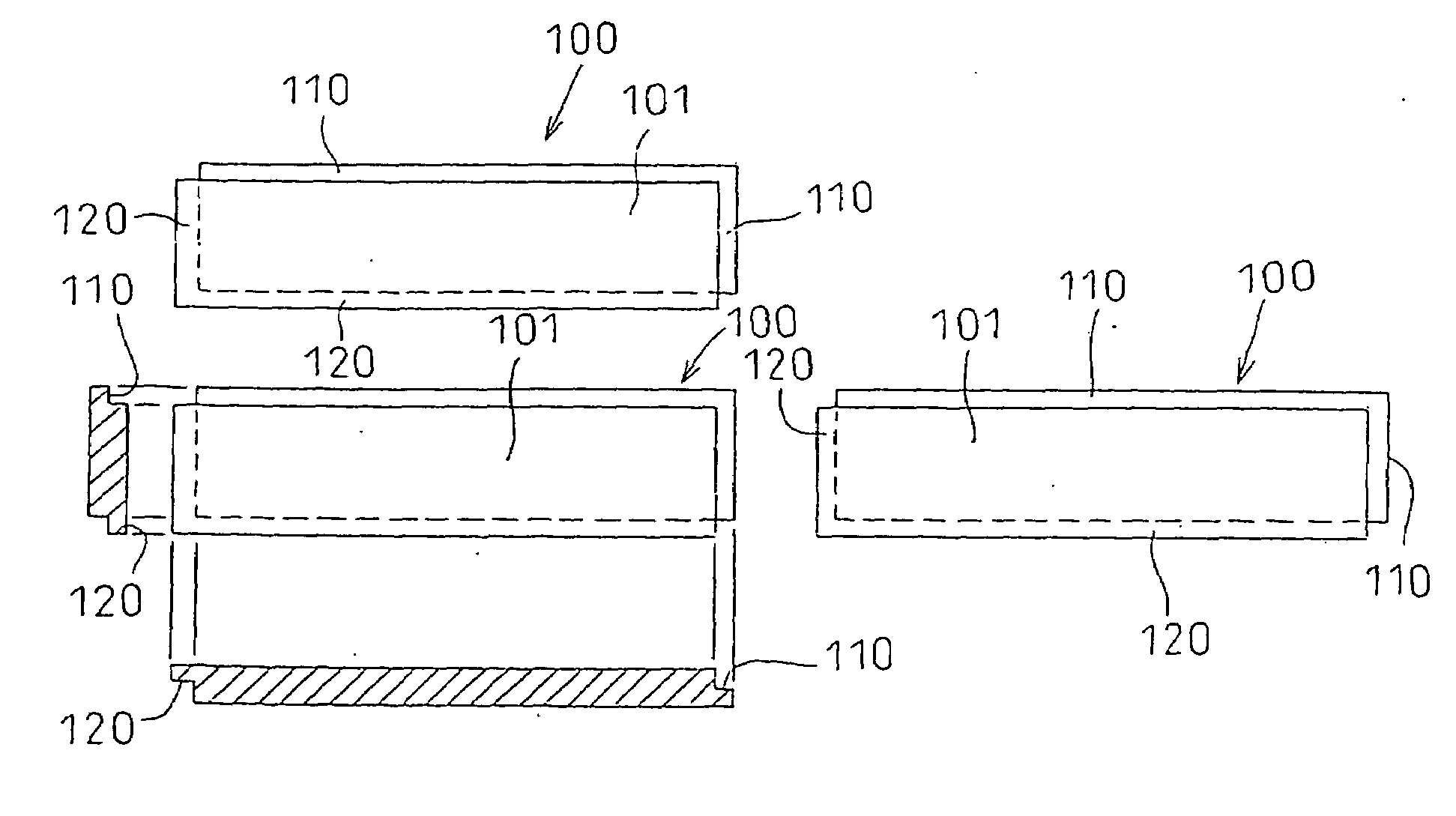
Consequently, when a number of sheets of the building boards are fastened onto the external wall portion of the building, the horizontal joint portions of the abutting building boards are not continuously connected to look straight-line, and are deviated in a vertical direction resulting in marring a designing feature of the external appearance of the construction.

Method used


Image

  • Printing apparatus and printing method for the same
  • Printing apparatus and printing method for the same
  • Printing apparatus and printing method for the same

Examples


Embodiment Construction

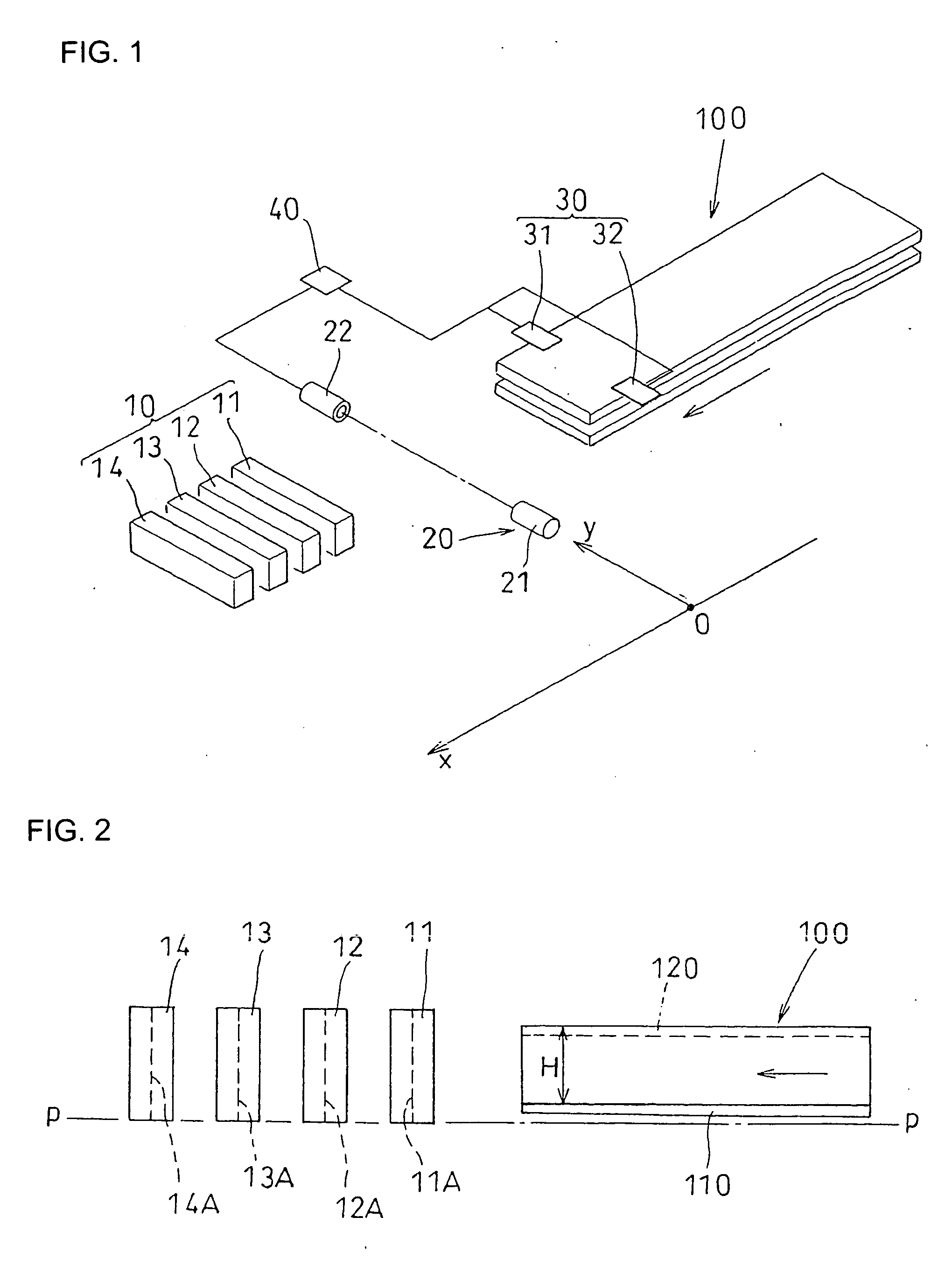
[0028]A printing apparatus according to the present invention will be schematically explained referring to FIG. 1. The printing apparatus of the present invention is provided with a printing head 10, a conveying apparatus (not shown) for moving an object to be printed, i.e., a building board (external wall board) 100, a position detecting device 20 for detecting whether the building board 100 has traveled through a predetermined position at an upstream side relative to the printing head 10, a measuring device 30 for measuring a printing width (width of the design surface in a direction of the shorter side) in a direction orthogonal to a longitudinal direction of the building board 100, an arithmetic unit 40 that creates printing control data while obtaining information from the position detecting device 20 and the measuring device 30, and transmits a printing control signal to the printing head 10. The printing apparatus of the present invention is a line-type printer where the prin...


PUM


Abstract

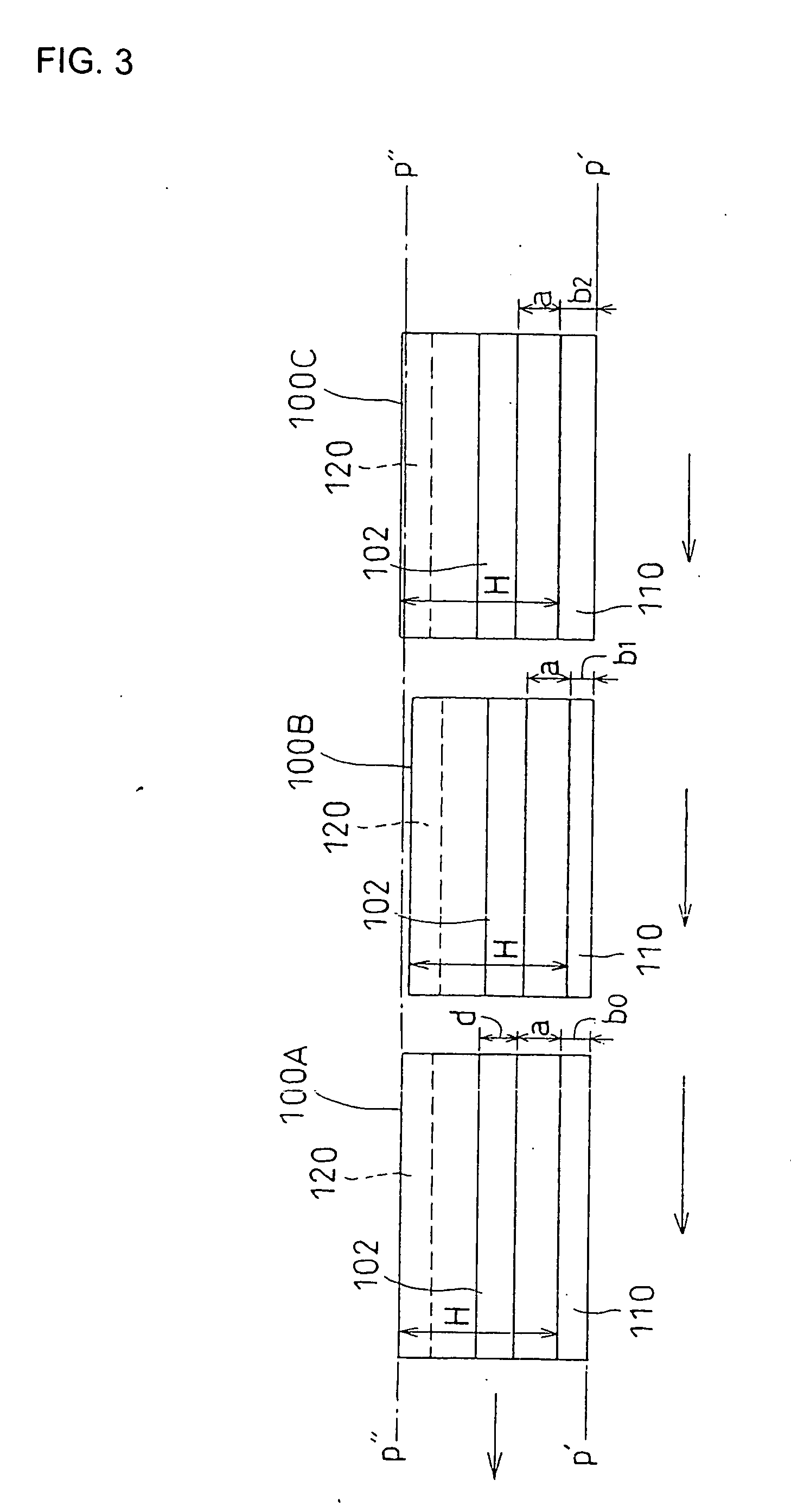
Horizontal joint portions of abutting building boards are constructed in a manner to look straight-line in an external appearance when constructed even in a case that the building board has a dimension error. A printing apparatus for printing a building board of a shiplap joint system composed of a design surface having a horizontal joint portion formed along a longitudinal direction of the building board and an upper and lower shiplap portions formed at an end portion of the building board includes a fixed printing head having a plurality of nozzles for performing printing operation by means of emitting a jet of ink toward the design surface of the building board, in which the printing head performs printing operation along a printing line spaced apart from an edge of the upper shiplap portion or the lower shiplap portion at a constant distance when performing the printing operation for the horizontal joint portion.

Description

BACKGROUND OF THE INVENTION[0001]1. Field of the Invention[0002]The present invention relates to a printing apparatus and a printing method for the same, and more particularly to a printing apparatus and a printing method for a building board.[0003]2. Description of the Related Art[0004]An example of a building board having an uneven surface with a design is partially shown in FIG. 6. The building board that is used as an external wall board has an entire shape of a long rectangular board, and the building board having a design, in which a number of rectangular convex portions are arranged in an orderly fashion in vertical and horizontal directions, such as a brick work, tiling, or the like is often used. A number of flat surfaces 101 of convex portions, and horizontal joint portions 102 and vertical joint portions 103 that continue around a periphery of the convex portions in a groove condition are formed on the design surface of the building board as shown in FIG. 6 in concrete fo...

Claims


Application Information

Patent Timeline
Patent Type & Authority Applications(United States)
IPC IPC(8): B41F17/00
CPCB41J3/407
Inventor YAMAUCHI, HIROYUKIYABE, TOMOYOSHI
Owner NICHIHA CORP
Learn More