
Cassette roller leveler with common back-up rolls

a leveler and cassette roller technology, applied in the field of levelers, can solve the problems of increasing the cost, time and maintenance of the leveler unit, and the curvature of the strip, so as to reduce the time to exchange, reduce the overall cost, and facilitate maintenance.

Active Publication Date: 2008-01-17
BUTECH BLISS
View PDF7 Cites 22 Cited by
  • Summary
  • Abstract
  • Description
  • Claims
  • Application Information

AI Technical Summary

Benefits of technology

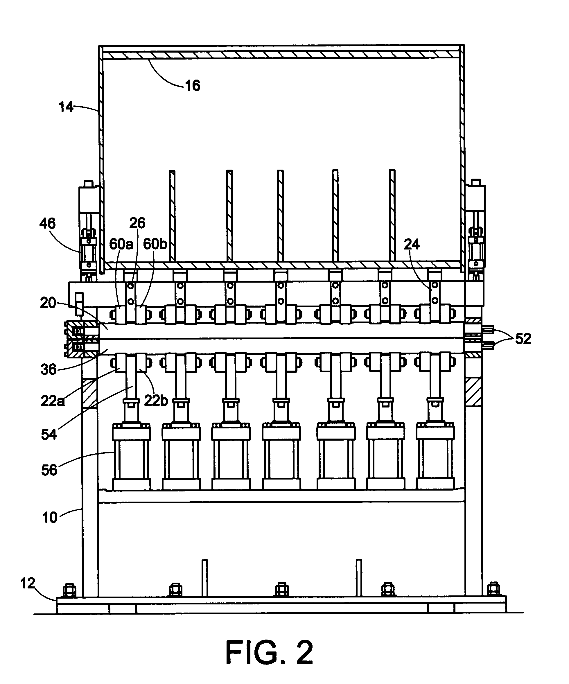
[0015] One aspect of the present invention is to eliminate the need to remove the back-up rolls when there is a need to insert a work roll cassette that utilizes a different work roll diameter.
[0016] Another aspect of the present invention is the reduction of time to exchange the work rolls, which results in more productivity and throughput for the line.
[0017] Still another aspect of the invention is the reduction in overall costs, as only one set of back-up rolls is required.
[0018] Yet another aspect of the present invention is the ease of maintenance, as the work roll faces are immediately accessible for cleaning when the rolls are extracted from the leveler; that is, there is no need to remove back-up roll to access the work rolls.

Problems solved by technology

Thus, the primary problem with strip coming off of a coil is the curvature which remains with the strip and which varies throughout the entire length of the coil as a function of the radius of any particular portion of the strip while in the coil.
In addition to strip curvature, other unwanted properties are sometimes impressed upon the strip during hot and / or cold rolling which render the problem of flattening strip much more complex.
However, if the rolls are over compensated against roll bending, the resultant is strip that is rolled thinner in the center than at the edges.
Thus, this combination of stacked rolls, including the back-up rolls, is removed and injected into the leveler as a unit, which increases costs, time and maintenance of the leveler unit.

Method used


Image

  • Cassette roller leveler with common back-up rolls
  • Cassette roller leveler with common back-up rolls
  • Cassette roller leveler with common back-up rolls

Examples


Embodiment Construction

[0025] One of the primary functions of a roller leveler is to remove curvature from a piece of metal strip, sheet or plate. Strip is defined to mean metal which is sufficiently narrow and is rolled sufficiently thin that it can be wrapped into a coil. A sheet is defined as metal that is, for whatever reason, cut into lengths rather than stored in coiled form. Plate is metal which is too thick, as a practical matter, to be formed into a coil.

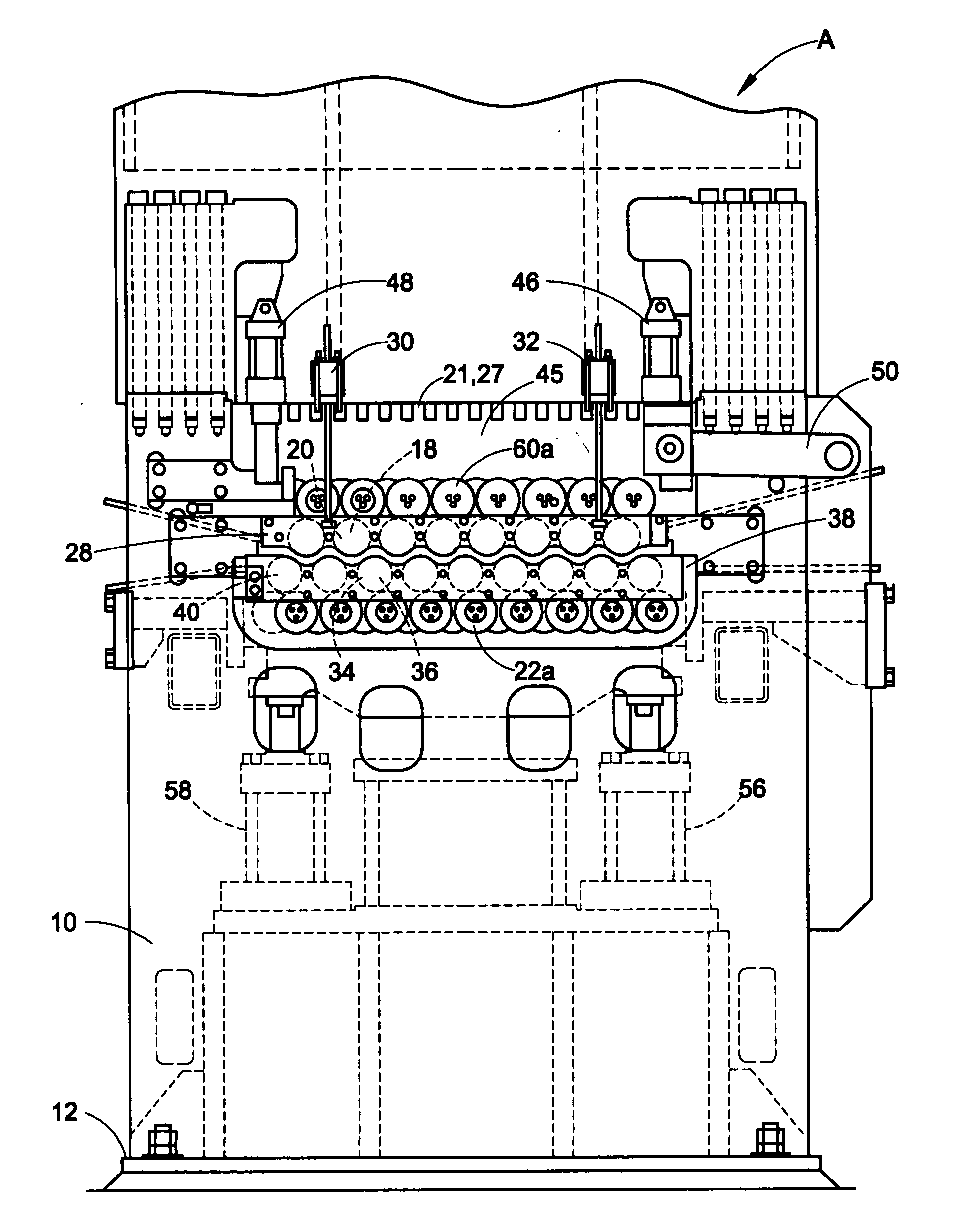
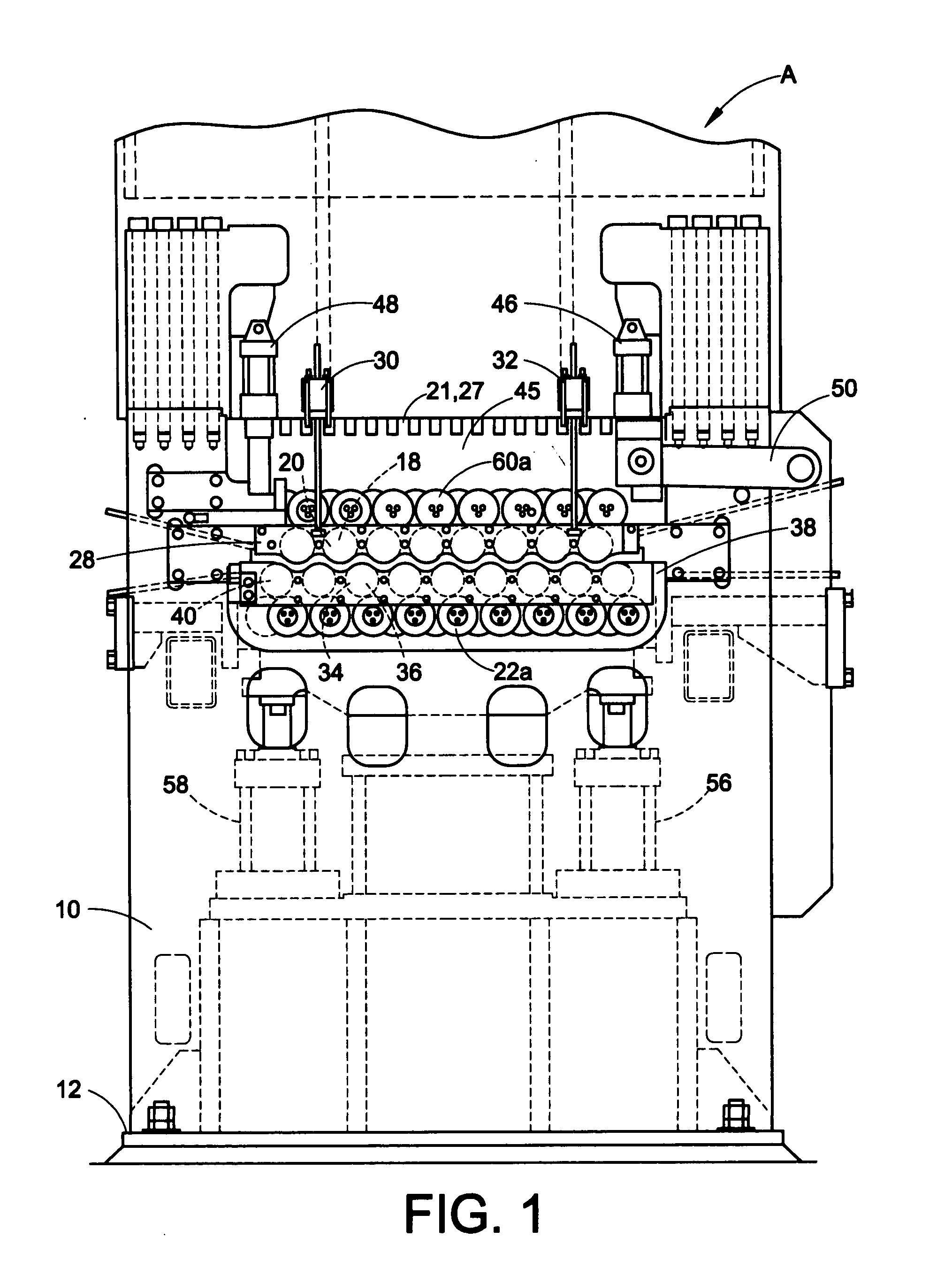
[0026] In the case of sheets and plates, the curvature would normally be of a substantially constant radius and the roller leveler means could be of the simplest form to flatten the sheet or plate. Referring to FIG. 1, for this operation, the roller leveler would theoretically require an upper work roller 20 and a pair of lower work rollers 36. It will be observed that a sheet moving from right to left is flexed downwardly between an upper work roller 20 and a lower work roller 36 to the right of roller 20 and then is reverse flexed between an u...


PUM

PropertyMeasurementUnit
Diameteraaaaaaaaaa

Abstract

A roller leveler having a frame; a first bank of upper and lower work rolls journalled in the frame via a work roll journal housing; and a bank of back-up rolls in contact with the work rolls to support the work rolls. The work rolls perform leveling on a work product passing through a gap formed between upper and lower work rolls. The back-up rolls are mounted to the roller leveler frame via a back-up housing. The back-up rolls are movable to allow the first bank of work rolls to be removed and a second bank of work rolls to be installed wherein the second bank of work rolls includes work rolls of a different diameter than the first bank of work rolls.

Description

CLAIM OF PRIORITY [0001] This application claims priority from Provisional Application Ser. No. 60 / 830,634, filed on Jul. 13, 2006, which is incorporated by reference herein.BACKGROUND [0002] The present embodiment relates to roller levelers. It finds particular application in conjunction with roller levelers with common back-up rolls, and will be described with particular reference thereto. However, it is to be appreciated that the present embodiment is also amenable to other like applications. [0003] A roller leveler typically includes multiple pairs of offset work rollers or rolls. Different size levelers can have different quantities of work rolls and back-up rolls. The upper rolls are typically offset one-half the distance between a pair of adjacent lower rolls. The metal strip passes between the upper and lower rolls. The number and spacing of the rolls depend on the thickness and strength of the metal strip. Typically, as the strip thickness decreases, the spacing of the roll...

Claims


Application Information

Patent Timeline
IPC IPC(8): B21D1/02
CPCB21D1/02
Inventor BUTA, JOHN R.
Owner BUTECH BLISS
Learn More