
Foundation system

a foundation system and foundation technology, applied in the field of building foundations, can solve the problems of increasing the chance of foundation failure, affecting the structural integrity of the foundation and the carried structure, and/or producing a non-level foundation, and achieve the effect of easy determination

Inactive Publication Date: 2008-01-10
TIMDIL
View PDF28 Cites 4 Cited by
  • Summary
  • Abstract
  • Description
  • Claims
  • Application Information

AI Technical Summary

Benefits of technology

[0017] The pilings are known in the art and are usually prepared in segments that may or may not be joined by rods, cables, sleeves or the like, which are driven hydraulically into the soil by resistance against the grade beams. By combining a plurality of the segments with the cooperating elements engaged in the ground, a piling is created. The cooperative engagement provides lateral stability of the piling stacking a plurality of such precast one on another. Installation of subsequent segments continues until adequate load capacity and depth are obtained. The pile penetration depth can be easily determined upon completion by simply counting the segments used. This method of installation provides an aligned, concrete underpinning pile of verifiable depth, installed under conditions with almost no clearance.

Problems solved by technology

Extreme cyclic weather changes greatly increase the chance for foundation failure.
This failure can be in the form of settlement or heave.
The changes in the supporting soil often result in damage to the structural integrity of the foundation and the carried structure and / or producing a non-level foundation.
Placing a foundation on the soil changes that footprint and distorts the equilibrium of the moisture underneath the foundation.
Left uncorrected, the settling of the soil and lack of stability of the foundation may result in loss of part or all of the value of the foundation and carried structure.
Repairs to “multiple owned” common slab units are almost impossible to coordinate.
Getting each individual unit to agree to spend the money, accept the fact that it has a problem and settle on one single contractor is a difficult task.
Most existing home warranties do not correct foundation movement unless the home is considered unsafe or uninhabitable.
Current methods of underpinning new homes to date have been very limited and the type of pier typically used in new construction is the same pier (poured in-place bell bottom piers) that has become somewhat obsolete in some parts of the U.S. to the foundation repair industry.
Although settlement may be a problem at times, it would appear that in expansive soils, the major cause of foundation damage to new homes is the result of soil heaving or swelling.
This is a very expensive foundation and even with these precautions there may be foundation issues during construction as a result of the failure of the poured piers.
Many new homes (less than 5 years old) are experiencing unacceptable foundation movement.
Many homes are experiencing failure that is considered unacceptable by the engineering community, building community and homeowners.

Method used


Image

  • Foundation system
  • Foundation system
  • Foundation system

Examples


Embodiment Construction

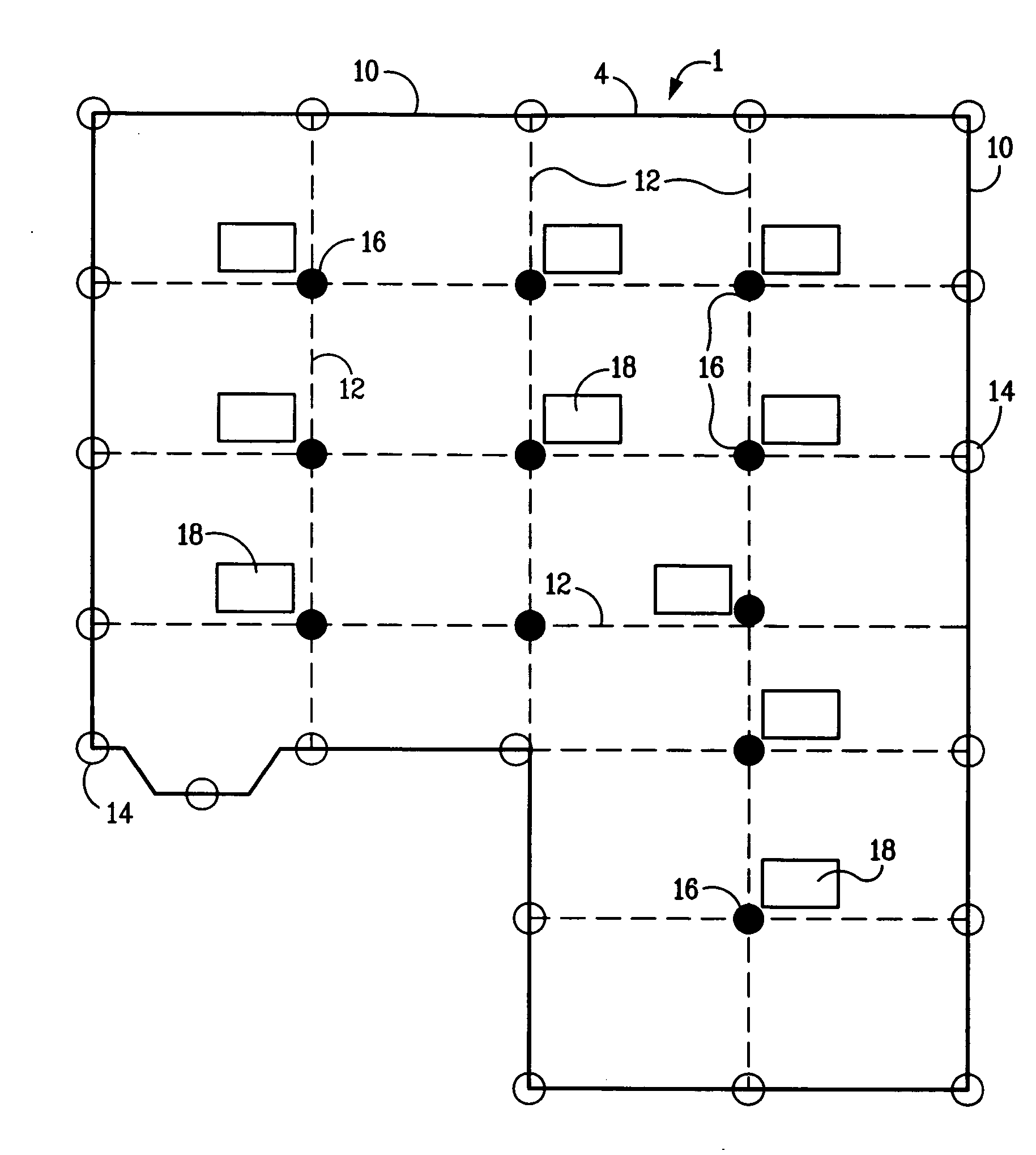
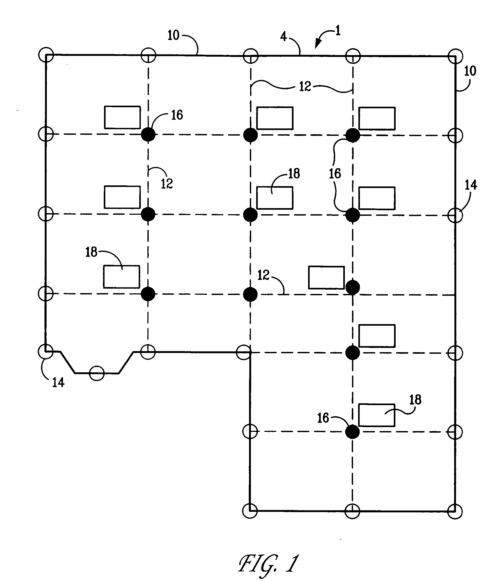
[0024] After on site soil borings are reviewed by a geotech engineer, the Potential Vertical Rise (P.V.R.) values are determined by the geotech. Based on P.V.R. values, the appropriate size void cartons are to be installed under all beams and throughout the entire concrete mat, except directly under the beams adjacent to the formed excess boxes. After an acceptable concrete curing time, a driven pile system is installed through the opening at the preformed box location. After pilings are driven to refusal or to a predetermined load capacity, the pilings are shimmed with various size spacers.

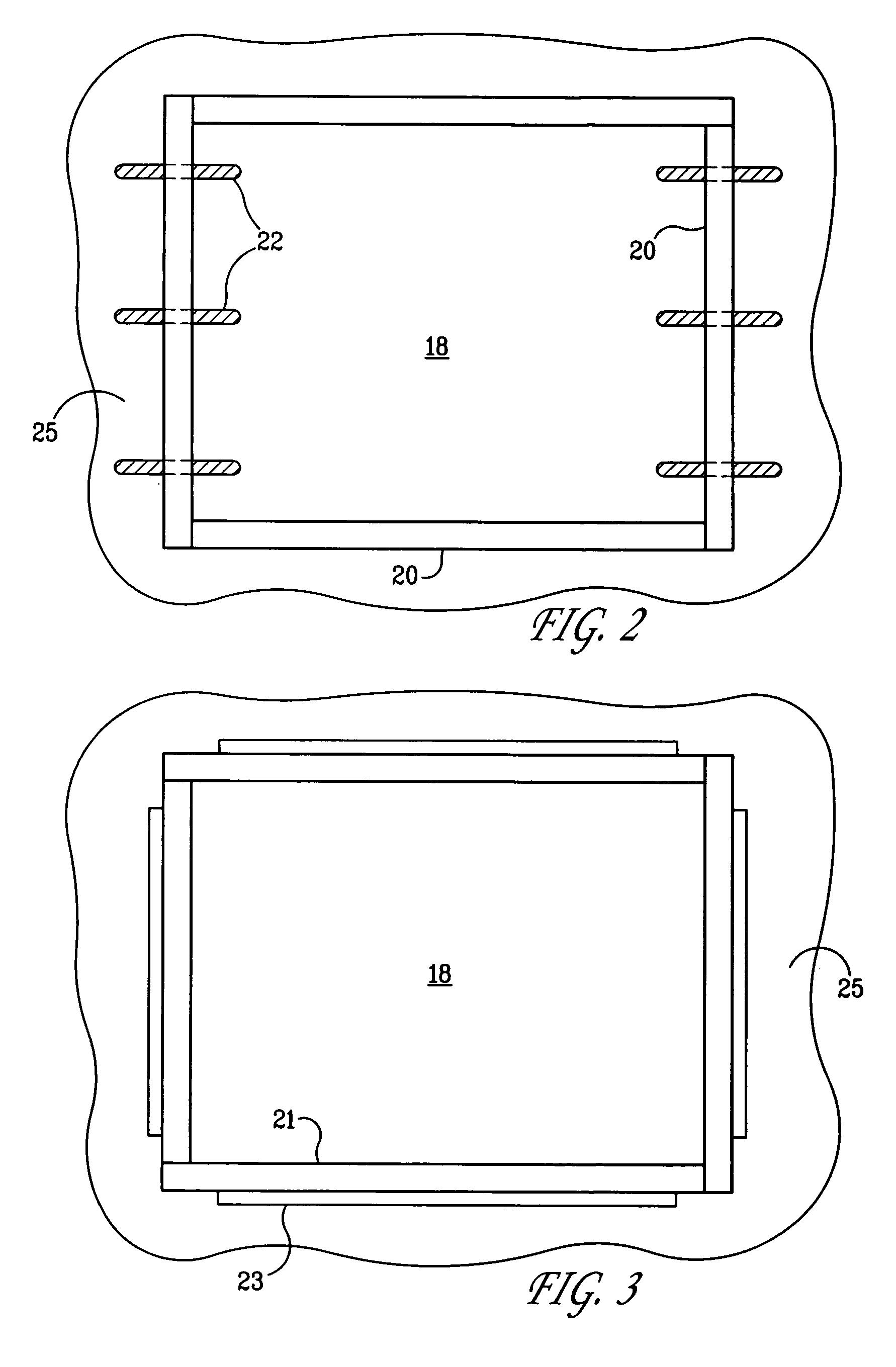
[0025] Prefabricated knockout boxes to form openings are installed on the interior portion of the slab prior to the pouring of the concrete. These boxes are preferably keywayed or doweled to help prevent slippage of the concrete patch after the piling is installed. After the concrete slab is poured and the concrete has had an acceptable curing time, the forms for the boxes are stripped when all ...


PUM


Abstract

A poured concrete slab foundation which has a first component comprising a poured concrete slab on soil, having at least one interior grade beam, grade beams about the periphery of said poured concrete slab, and an array of openings along and adjacent to each said interior grade beam; a second component comprising an array of driven piles in the soil below said interior and periphery grade beams; and a third component comprising poured concrete closures in said openings, which is made by preparing a poured concrete slab on soil, having at least one interior grade beam, grade beams about the periphery of said poured concrete slab, and an array of openings along and adjacent to each said interior grade beam; driving an array of pilings in the soil below said interior grade beams adjacent to the openings and the periphery grade beams and pouring concrete closures in said openings.

Description

[0001] This application claims the benefit of provisional application 60 / 678,059 filed May 5, 2005.BACKGROUND OF THE INVENTION [0002] 1. Field of the Invention [0003] The invention relates to building foundations. More specifically, it relates to a method for building a poured concrete foundation which more effectively isolates the foundation from the ground heave of the soil on which it is built. [0004] 2. Related Art [0005] Many types of structures, such as residential homes, commercial buildings and industrial equipment, are erected on foundations or slabs made of concrete poured on top of soil. These foundations are typically concrete slabs and may include a concrete footing that is wider and deeper than the foundation to spread the load of the foundation and carried structure. Ultimately the structural integrity and the level of the foundation and the carried structure are dependent on the stability of the underlying soil. Extreme cyclic weather changes greatly increase the cha...

Claims


Application Information

Patent Timeline
IPC IPC(8): E02D31/02
CPCE02D27/01
Inventor MCCLURE, GARY W.CATES, CHRISTOPHER H.DUTTON, KENNETH R.DUTTON, JAMES A.
Owner TIMDIL
Learn More