Failsafe watercraft lift with convertible leveling system

Inactive Publication Date: 2008-01-10
SUNSTREAM CORP
View PDF45 Cites 22 Cited by
  • Summary
  • Abstract
  • Description
  • Claims
  • Application Information

AI Technical Summary

Benefits of technology

[0014] The pontoon includes a buoyant port pontoon portion having an end portion and a buoyant starboard pontoon portion having an end portion. The port and starboard pontoon portions are spaced apart sufficient to receive the watercraft therebetween. The pontoon further includes a buoyant connection pontoon portion having the end portions of the port and starboard pontoon portions attached thereto. The combined buoyancy of the port pontoon portion, the starboard pontoon portion and the connection pontoon portion is sufficient hold the watercraft out of the water when the watercraft is positioned on the support bunk with the watercraft lift in the raised position when all pressurized air is released from the internal chamber the air tank.
[0017] The watercraft lift may further include a lock operable to lock the pivot arm relative to the pontoon when the lifting cradle is in the raised position to prevent downward movement of the pivot arm and thereby movement of the lifting cradle to the lowered position. The lock includes a selectively rotatable upright member having an engagement member attached thereto, the rotatable member being rotatable between a locked position and an unlocked position. In the locked position the engagement member is positioned in locking engagement with the pivot arm to prevent downward movement of the pivot arm and thereby movement of the lifting cradle to the lowered position. In the unlocked position the engagement member is positioned out of locking engagement with the pivot arm to allow downward movement of the pivot arm and thereby movement of the lifting cradle to the lowered position. The lock may include a security member which when engaged prevents rotation of the rotatable member out of the locked position.

Problems solved by technology

It reduces the possibility of the boat breaking free from its moorage and floating adrift or running aground.
In certain situations where the water fluctuation is high, water depth is too deep, or permanent mounting is undesired, floating watercraft lifting devices are used.
This device, however, is limited in that the watercraft will not be raised or lowered in a horizontal position which is undesirable to many users.
While this device raises the boat out of the water, it has many disadvantages including a complicated rope tying configuration for stabilizing, non-horizontal lifting by raising the bow of the watercraft before the stern, and incompatibility with all boats by only fitting boats with outboard and inboard / outboard motors.
While addressing these stability issues, the lift suffers from a number of disadvantages including the lack of a means for keeping the lift stable if air pressure is lost in one or all pontoon chambers, the ability to fit in a narrow boat slip, and the lack of reserve buoyancy to keep the device from sinking if all air pressure is lost.
These fixed stabilizing brackets are undesirable for marina operations and limit the ease of portability for these lifts.
While allowing for portability and side tie capabilities, these lifts do not raise the watercraft in a horizontal position and have similar disadvantages to Rutter and Moody.
In addition to the above stated short comings, the floating watercraft lifts of Rutter, Moody, Sainz, Hydrohoist, Shoremaster and Air Berth may inadvertently lower the watercraft into the water if air pressure is not maintained in one or all air chambers.
In this case the watercraft will become susceptible to the damaging elements described above.
Another difficulty facing floating watercraft lift manufacturers is the multitude of mounting scenarios.

Method used


Image

  • Failsafe watercraft lift with convertible leveling system
  • Failsafe watercraft lift with convertible leveling system
  • Failsafe watercraft lift with convertible leveling system

Examples


Embodiment Construction

[0040] This section illustrates aspects of the invention, and points out certain preferred embodiments of these aspects. This section is not intended to be exhaustive, but rather to inform and teach the person of skill in the art who will come to appreciate more fully other aspects, equivalents, and possibilities presented by invention, and hence the scope of the invention is set forth in the claims, which alone limit its scope.

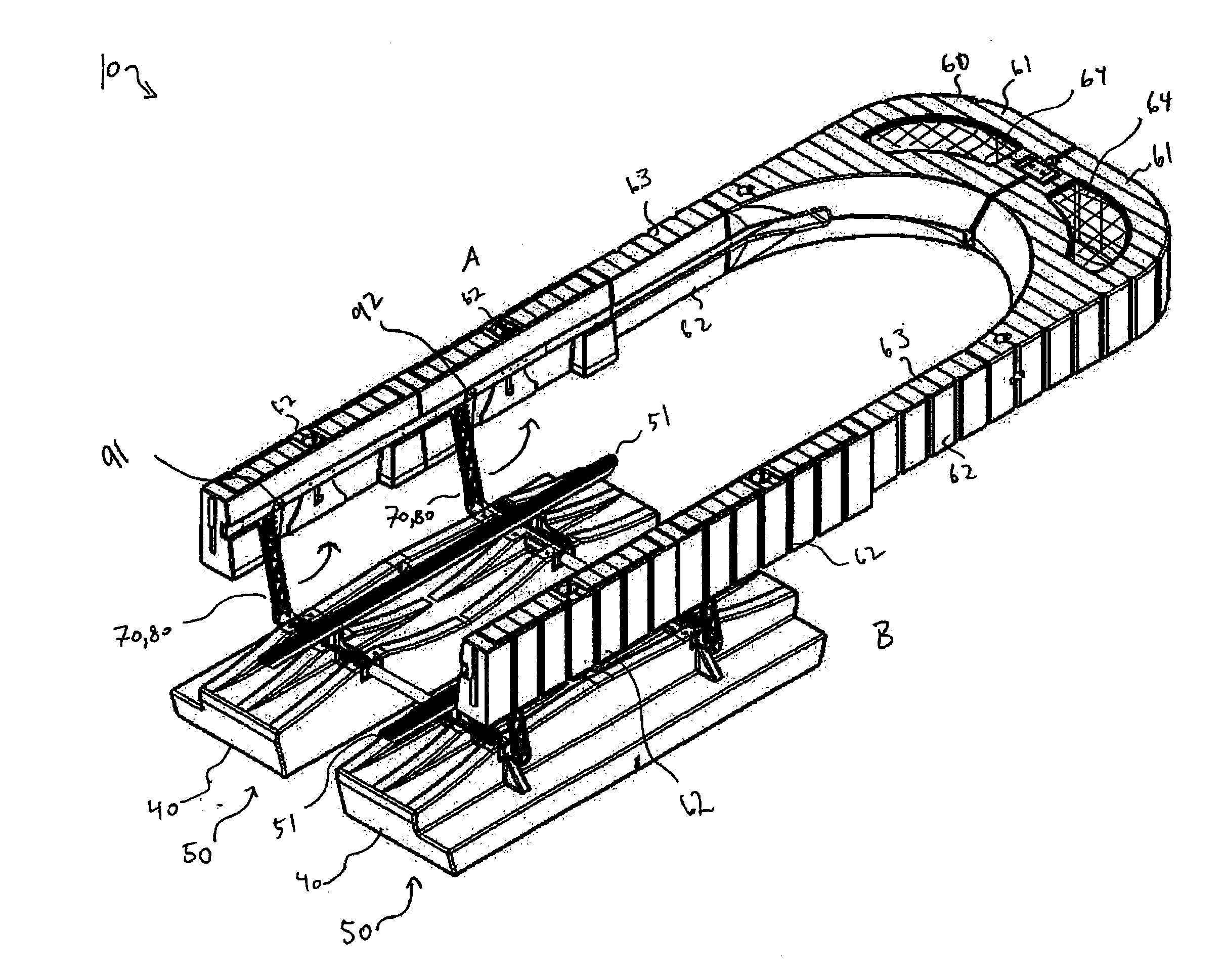
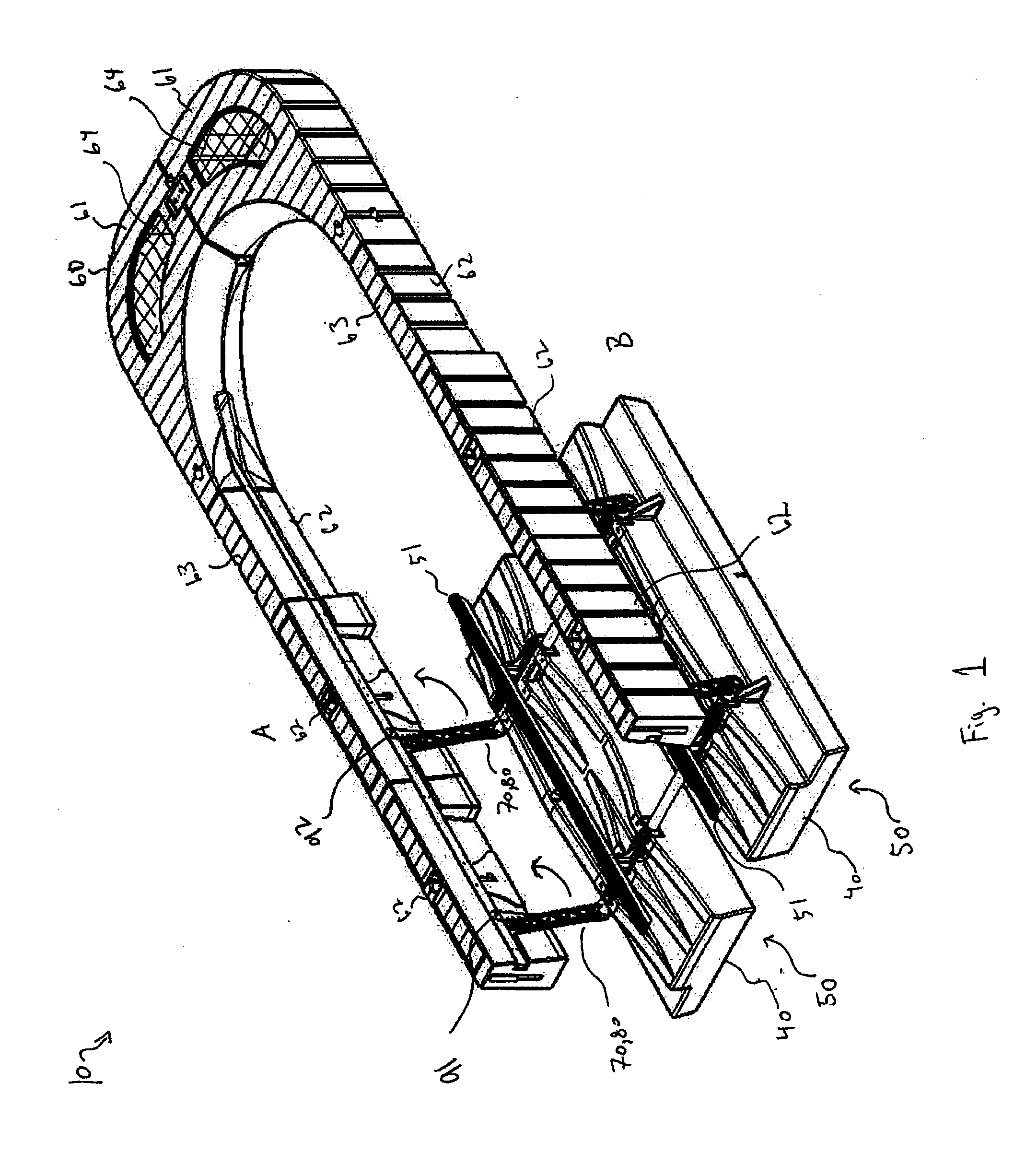
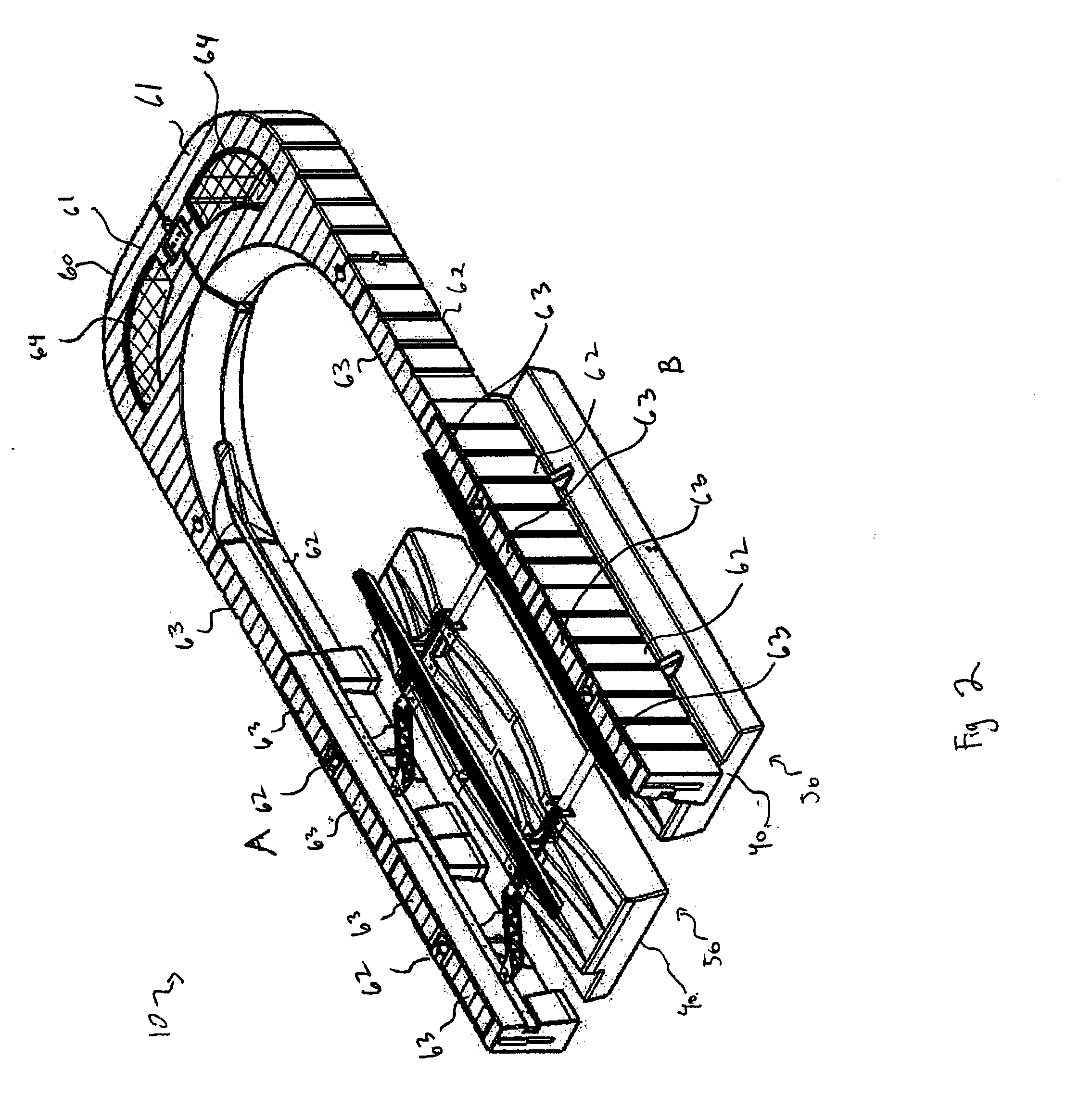
[0041] Several embodiments of the invention are set forth in the following description: FIGS. 1 through 20 provide a thorough understanding of such embodiments. One skilled in the art will understand that the present invention may be practiced without several of the details described herein. In the following description of the embodiments, it is understood that a watercraft includes any vehicle that is at least partially waterborne, which includes boats and similar vessels, but may also include amphibious vehicles including various amphibious automobiles or ...


PUM


Abstract

A watercraft lift for raising and lowering a watercraft in water, including a buoyant pontoon, a lifting cradle and at least one pivot arm. The lifting cradle includes at least one air tank and a support bunk configured to receive and support the watercraft. The air tank has an internal chamber configured to receive and release pressurized air. The internal chamber has sufficient internal volume that when sufficient pressurized air is received therein the air tank has sufficient buoyancy to lift the lifting cradle to a raised position with the watercraft out of the water when positioned on the support bunk and that when sufficient pressurized air is released from the internal chamber the air tank loses sufficient buoyancy to sink the lifting cradle to a lowered position sufficiently submerged to receive and deploy the watercraft. The pivot arm is pivotally connected to the pontoon and pivotally connected to the lifting cradle to guide movement of the lifting cradle between the lowered position and the raised position.

Description

FIELD OF THE INVENTION [0001] The invention generally relates to an apparatus and method for lifting watercraft out of the water. DESCRIPTION OF THE RELATED ART [0002] The use of watercraft lifting devices is well known. Out-of-water storage prevents damage resulting from boat contact with docks, other craft or floating debris. It reduces the possibility of the boat breaking free from its moorage and floating adrift or running aground. Out-of-water storage also lessens boat damage associated with long-term exposure to water and water-based pollutants and the attachment of barnacles or other marine growth to the boat's hull. Once a boat is lifted it can be maintained in its position for extended periods of time, relieving the user of maintenance concerns. In certain situations where the water fluctuation is high, water depth is too deep, or permanent mounting is undesired, floating watercraft lifting devices are used. A number of floating lift designs are currently known that provide...

Claims


Application Information

Patent Timeline
IPC IPC(8): B63C3/06
CPCB63C3/06B66F7/08B66F7/0641B66C1/62
Inventor HEY, KENNETH E.KLOSTER, BRYCE M.
Owner SUNSTREAM CORP
Why Eureka
Try Eureka