Device for the assembly of a motor vehicle clutch

a technology for motor vehicles and clutch covers, applied in metal-working hand tools, metal-working equipment, metal-working hand tools, etc., can solve the problems of clutch cover adjustment, inability to achieve sufficient precision of pretensioning means,

Inactive Publication Date: 2014-02-25
KLANN SPEZIAL WERKZEUGBAU
View PDF9 Cites 9 Cited by
  • Summary
  • Abstract
  • Description
  • Claims
  • Application Information

AI Technical Summary

Benefits of technology

[0011]To remove the clutch, three of the mounting bolts can be removed without warping of the clutch cover taking place, and they can be replaced with three centering bolts. If the clutch cover is mounted, for example, with eight mounting bolts on the driven plate, four of the mounting bolts can be removed. The remaining mounting bolts remain in the driven plate for fixing the clutch cover, so that the clutch cover is still held sufficiently on the driven plate. The base plate is now attached to the centering bolts screwed stationarily into the driven plate through the through holes.
[0025]If a bearing bore is present in the crankshaft, the centering tool can be used as a centering or aligning aid for the pretensioning means. The centering tool is provided for this purpose with a centering pin, which is fittingly inserted into the bearing bore of the crankshaft concentrically with the driven plate before the pretensioning means is attached. The carrier plate, which engages the centering tool, is thus also aligned concentrically with the driven plate. When the pretensioning means with its pressing screw is pushed over the centering tool, this pressing screw is also aligned concentrically with the driven plate, so that the base plate with its adjusting slots can be caused to engage the centering bolts screwed into the driven plate in a simple manner. Provisions are made for this for the completely mounted centering tool with its guide tube, the tie rod and the tensioning nut to be able to be pushed through the central through hole of the pressing screw.

Problems solved by technology

The drawback of this construction is that the clutch cover is to be aligned concentrically via its draw hook at the pretensioning means before the plate spring is pretensioned by the pressing screw.
However, since the draw hooks are arranged in adjusting slots and have a considerable clearance in both the circumferential direction and the radial direction, such a concentric alignment of the clutch cover in relation to the pressing screw arranged concentrically in the base plate of the pretensioning means is not possible with sufficient accuracy.
This in turn has the drawback that the clutch cover must be adjusted in the state in which it is attached to the driven plate, because when the clutch cover is mounted eccentrically in relation to the pressing screw, the clutch cover is also arranged eccentrically in relation to the centering tool and consequently also eccentrically in relation to the carrier plate when the centering tool is arranged in the through hole of the pressing screw.

Method used


Image

  • Device for the assembly of a motor vehicle clutch
  • Device for the assembly of a motor vehicle clutch
  • Device for the assembly of a motor vehicle clutch

Examples


Embodiment Construction

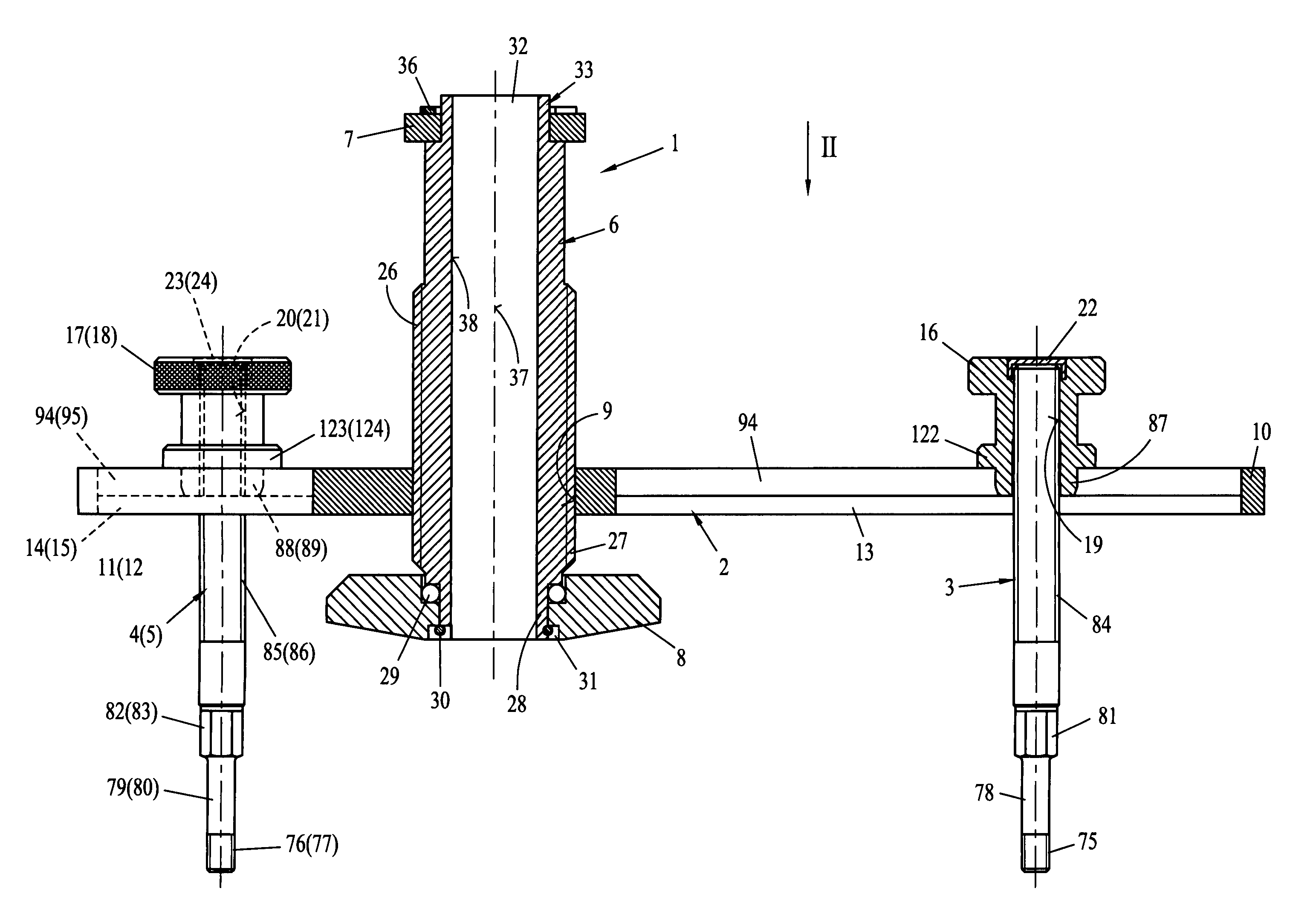
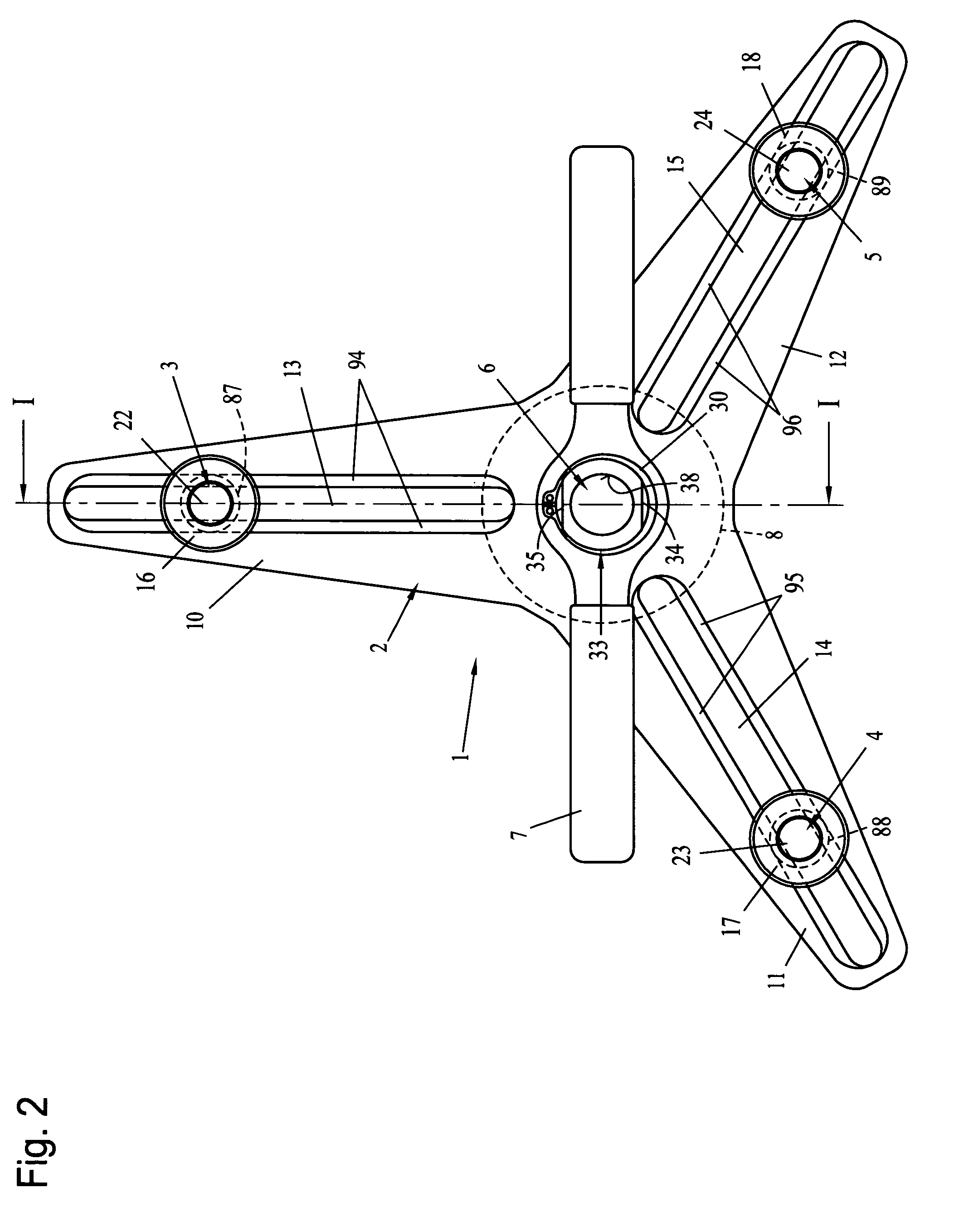
[0036]Referring to the drawings in particular, FIGS. 1 and 2 show as an example an embodiment of a pretensioning means 1 according to the present invention, which comprises in this exemplary embodiment a base plate 2, three centering bolts 3, 4 and 5 as well as a pressing screw 6 with an actuating lever 7 and a thrust collar 8.

[0037]As is apparent especially from FIG. 2, the pressure plate 2 has an approximately star-shaped base and is provided with a central through thread 9. The base plate 2 forms three draw arms 10, 11 and 12, which are arranged in a star-shaped pattern and have a radially extending adjusting slot 13, 14 and 15. These adjusting slots 13, 14 and 15 are arranged, together with their draw arms 10, 11 and 12, offset at an angle of 120° in relation to one another.

[0038]The adjusting slots 13, 14 and 15 are used for the radially displaceable mounting of the respective associated centering bolt 3, 4 and 5. The centering bolts 3, 4 and 5 are of an identical design and ha...


PUM

PropertyMeasurementUnit
angleaaaaaaaaaa
pressureaaaaaaaaaa
areaaaaaaaaaaa

Abstract

A device for the assembly of a motor vehicle clutch (99), has a pretensioning device (1) for clamping a plate spring (102), which is arranged in a clutch cover (100) of the motor vehicle clutch (99) together with a pressure plate (104) and by which the pressure plate (104) is pressed against a carrier plate (119) of the clutch (99) during operation. The clutch cover (100) is mounted stationarily during operation by a plurality of mounting bolts on a driven plate (97) and wherein the pretensioning device (1) has a base plate (2) with a central pressing screw (6), which is axially adjustable centrally through the base plate (2) against the plate spring (102) for pretensioning the plate spring (102). To securely and concentrically attach the pretensioning device (1), centering bolts (3, 4, 5) are provided, which can be replaced with individual mounting bolts of the clutch cover (100) and which can be screwed stationarily into the mounting threads (90) of the driven plate (97) through the mounting holes (101) of the clutch cover (100). The centering bolts (3, 4, 5) engage adjusting slots (13, 14, 15) of the base plate (2). The slots extend radially in relation to the pressing screw (6), wherein the base plate (2) can be fixed to the centering bolts (3, 4, 5) in the axial direction via tightening nuts (16, 17, 18).

Description

CROSS REFERENCE TO RELATED APPLICATIONS[0001]This application claims the benefit of priority under 35 U.S.C. §119 of German Application DE 20 2004 014 423.9 filed Sep. 14, 2004, the entire contents of which are incorporated herein by reference.FIELD OF THE INVENTION[0002]The present invention pertains to a device for the assembly of a motor vehicle clutch, comprising a pretensioning means for clamping a plate spring, which is arranged in a clutch cover of the motor vehicle clutch together with a pressure plate and by which the pressure plate is pressed against a carrier plate of the clutch during operation, wherein the clutch cover is mounted stationarily during operation on a driven plate by means of a plurality of mounting bolts, and wherein the pretensioning means has a base plate with a central pressing screw, which can be axially adjusted centrally through the base plate against the plate spring for pretensioning the plate spring, and which is provided with a central through ho...

Claims


Application Information

Patent Timeline
Patent Type & Authority Patents(United States)
IPC IPC(8): B25B27/00B23P19/04B25B27/073
CPCB25B27/0064Y10T29/53843Y10T29/53878Y10T29/53909Y10T29/53978
Inventor KLANN, HORST
Owner KLANN SPEZIAL WERKZEUGBAU
Why Eureka
Try Eureka