
Multifunction surgical probe

a multi-functional, surgical probe technology, applied in the field of surgical probes, can solve the problems of delay and inefficiency, prior art systems do not provide a means by which a surgeon can perform surgery,

Inactive Publication Date: 2008-01-03
ALCON INC
View PDF22 Cites 66 Cited by
  • Summary
  • Abstract
  • Description
  • Claims
  • Application Information

AI Technical Summary

Benefits of technology

[0009]The embodiments of the multifunction surgical probe of the present invention substantially meet these needs and others. Embodiments of the present invention can comprise a switching mechanism within a probe assembly that duplicates or replaces the prior art laser firing functionality of a surgical footswitch and, in some embodiments, the stand-by-to-ready laser state switching functionality of the controls on a main surgical console. One embodiment of the multifunction surgical probe of this invention is a surgical probe comprising: a handpiece, operable to receive a light beam from a laser; and a firing...

Problems solved by technology

A delay and inefficiency are imposed by requiring the assistant or the surgeon to move to the control panel to prepare the laser.
Prior art systems do not provide a means by which a surgeon can, independently of an assistant, easily place a laser in a ready position and continue with the laser surgery without having to detract attention from the surgery.
However, even the footswitch disclosed in that application does not provide a surgeon the increased precision and synchronous control of a surgical laser that can be provided by a handheld probe having the ability to control the laser using controls incorporated into the handheld probe.

Method used


Image

  • Multifunction surgical probe
  • Multifunction surgical probe
  • Multifunction surgical probe

Examples


Embodiment Construction

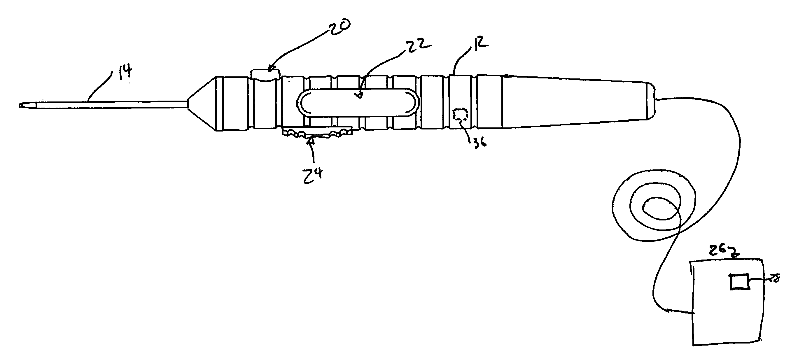
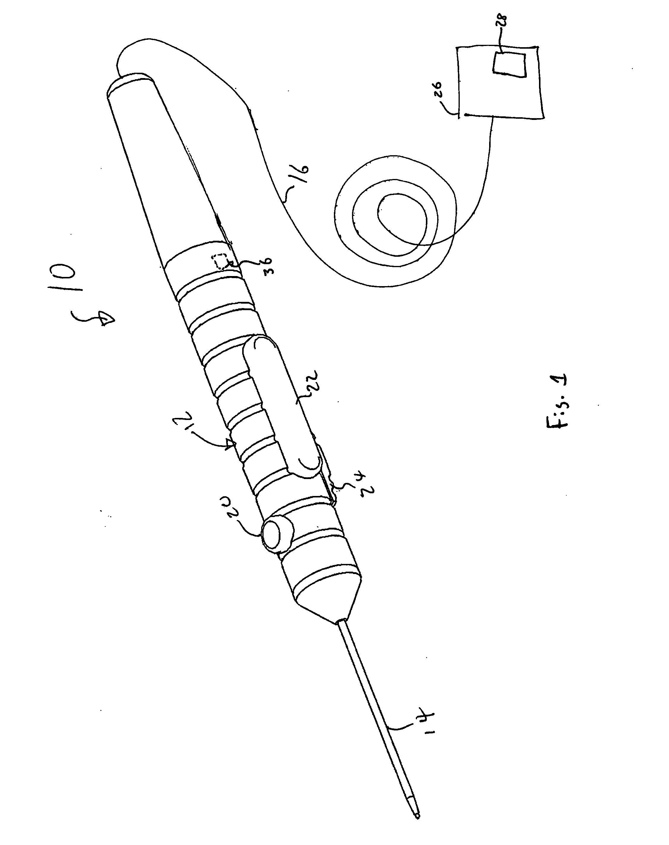
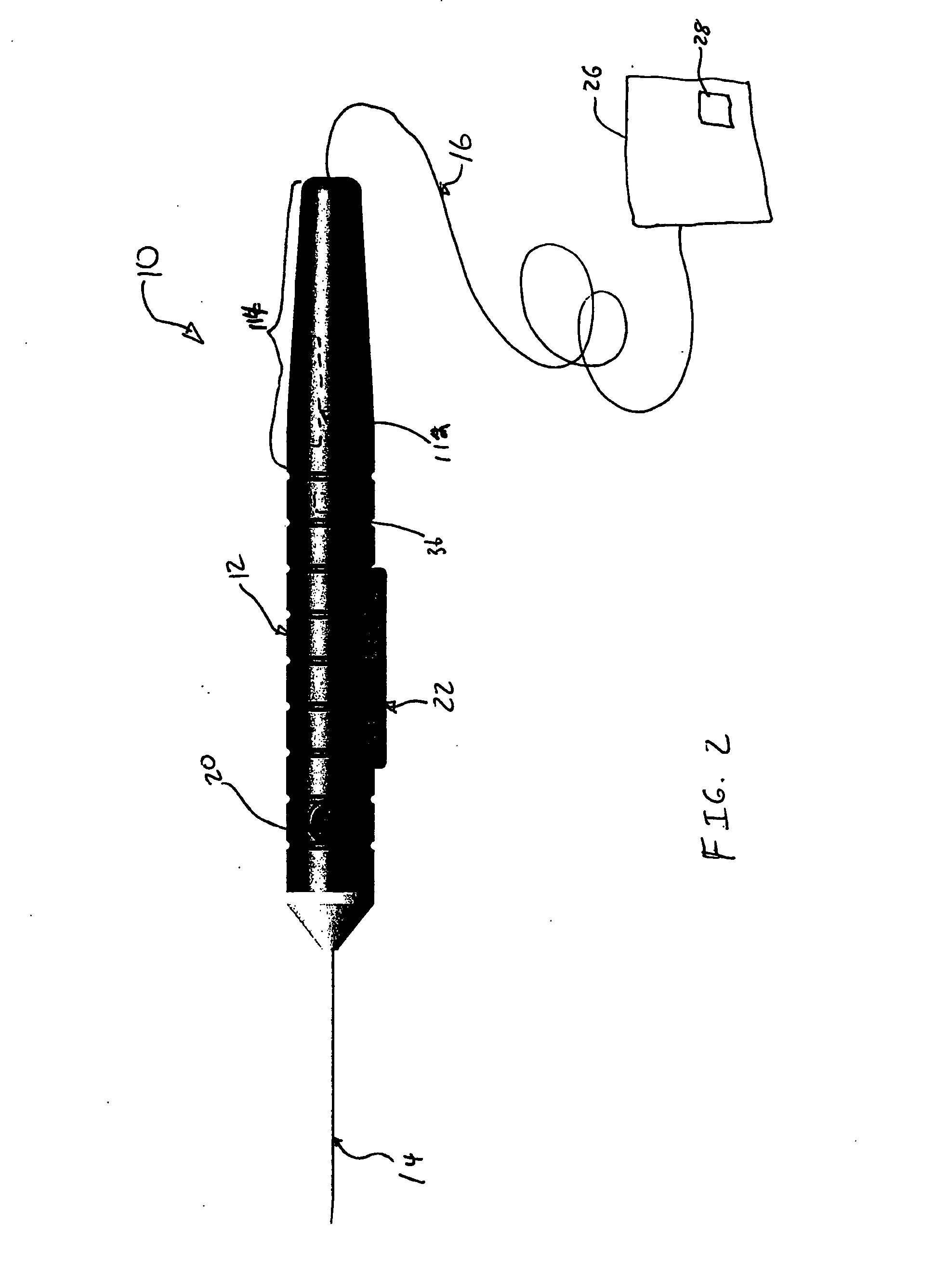
[0020]Preferred embodiments of the present invention are illustrated in the FIGUREs, like numerals being used to refer to like and corresponding parts of the various drawings.

[0021]The various embodiments of the present invention provide a multifunction surgical probe that allows a surgeon to place a surgical laser in a ready condition, fire the laser once it is in the ready condition, or both from the probe handpiece. Embodiments can comprise one or more switches for controlling various functions.

[0022]In the prior art, surgical lasers, such as an endolaser, are typically fired by a surgeon using a footswitch. The surgeon uses a surgical probe for receiving and directing a laser beam of light from the surgical laser into a patient's eye, but the laser itself is typically controlled via the footswitch and controls on a surgical console (that typically houses the surgical laser). The probe, with which the surgeon is directing the application of the laser beam, is thus physically disp...


PUM

PropertyMeasurementUnit
Poweraaaaaaaaaa
Mechanical propertiesaaaaaaaaaa

Abstract

A multifunction surgical probe is disclosed, one embodiment comprising: a handpiece, operable to receive a light beam from a laser; and a firing switch operable to provide a firing control signal to cause the laser to fire and emit the light beam. The surgical prove can further comprise an interface communicatively coupled to the firing switch and operable to communicate the firing control signal to the laser. The laser can be operably coupled to a surgical console operable to control the laser, and the interface can be communicatively coupled to the firing switch and operable to communicatively couple the surgical probe to the surgical console and to communicate the firing control signal to the surgical console. The surgical console can be operable to control the laser based on the firing control signal. The surgical probe can also comprise an interlock switch operable to prevent the firing switch from firing the laser and a standby switch operable to produce a standby control signal to switch the laser between a stand-by and a ready state. The firing switch can be a progressively actuated switch operable to, at a first point in its range of motion, provide an initializing control signal operable to initialize the laser in preparation for firing and then, at a second point in its range of motion, provide the firing control signal to cause the laser to fire.

Description

TECHNICAL FIELD OF THE INVENTION[0001]The present invention relates generally to surgical probes, and more particularly, to a multifunction surgical probe operable to provide a surgeon independent control of an ophthalmic laser surgical system.BACKGROUND OF THE INVENTION[0002]Handheld probes are used with a variety of electrical and mechanical equipment and, in particular, have become an accepted part of microsurgical and ophthalmic systems. Accordingly, the present handheld probe invention will be described in terms of its use with microsurgical systems and, in particular, its use with ophthalmic laser surgical systems.[0003]When surgically treating a patient, for example, during ophthalmic surgery, a surgeon may use a complex patient treatment apparatus / surgical system that may require the control of a variety of different pneumatic and electronically driven subsystems. Typically, the operation of these subsystems is controlled by a microprocessor-driven console. The microprocesso...

Claims


Application Information

Patent Timeline
IPC IPC(8): A61B18/18
CPCA61B18/22A61B2018/00928A61F9/008B23K26/0096A61F2009/00863A61F2009/00874A61F9/00821
Inventor DACQUAY, BRUNOHORVATH, CHRISTOPHERROMODA, LASZLOPASTRANA, ARMANDO
Owner ALCON INC
Learn More