Image forming apparatus

Inactive Publication Date: 2008-01-03
RICOH KK
View PDF22 Cites 11 Cited by
  • Summary
  • Abstract
  • Description
  • Claims
  • Application Information

AI Technical Summary

Benefits of technology

[0024]An image forming apparatus according to one aspect of the present invention includes an image carrier that carries a toner image; and an endless belt that is extended over a plurality of extending rollers, and carries either one of the toner image transferred from the image carrier and a transfer sheet. The endless belt includes a front-side reinforcing member and a rear-side reinforcing member fixed over an approximately entire circumference on front and back surfaces of both edges in a width direction, and a guide member for preventing meandering fixed over an approximately entire circumference on the rear-side reinforcing member. Each of the extending rollers includes a step portion provided in an end area in an axial direction facing to the rear-side reinforcing member, the step portion having a diameter smaller than a center area in the axial direction. The front-side reinforcing member has a width wider than a width of the rear-side reinforcing member.

Problems solved by technology

For example, if the endless belt is deviated even slightly in a width direction or meandering, degradation in image quality is inevitable.
However, a load occurring due to this repeated force on the A portion is so significant that a crack tends to occur on the intermediate transfer belt 100 from the A portion as a starting point.
With the repetition of load and separation of the shifting force, a crack tends to occur on the belt.
However, with this configuration, a corner portion B of the roller step portion 111 and the intermediate transfer belt 100 rub in a sliding manner, thereby wearing the belt and causing a crack to tend to occur.
Moreover, such a belt crack tends to occur from the end in a width direction.
Once a small crack occurs at the end of the belt, the crack is spread.
Once a crack occurs at the belt end, the rear-side reinforcing member 105 almost cannot prevent the spread of the crack.
A crack prevention effect of the front-side reinforcing member is stronger than that of the rear-side reinforcing member but, if the width of the front-side reinforcing member is narrower than the width of the rear-side reinforcing member, a crack may occur outside of the reinforcing members, thereby posing a problem in durability.
Thus, once a crack occurs, an effect of preventing a spread of the crack is weak.
When the intermediate transfer belt 100 becomes wavy, a detection failure may occur when a toner pattern is formed on the belt and this toner pattern is detected by a sensor.
Furthermore, a difference in circumferential length between portions in a belt width direction will bring a difference in belt running speed.
As a result, the belt tends to be shifted inward in a width direction, thereby causing a crease in the belt.
However, since there is no member for reinforcing a joint between the ends in a circumferential direction of the guide member 101, a crack tends to occur at a portion of the belt corresponding to the joint.
Therefore, when reinforcing members are provided on both of the front and back surfaces of the belt, although the crack prevention effect against a crack from the belt end surface is strong, an effect of preventing a crack occurring from a step portion inside of the reinforcing member is weak.
This conventional technology, however, is to ensure flatness of the belt by providing a step at the roller end for blade cleaning, and no mention is found about the occurrence of a crack due to the step and its prevention or about a front-side reinforcing tape.
Therefore, an effect of preventing a crack occurring from a step between an inner edge of the reinforcing tape and a belt surface cannot be expected.
However, only a guide member is provided on the back of a belt, and no rear-side reinforcing tape is provided.
Therefore, an effect of preventing a crack occurring from a step portion between an inner edge of the front-side reinforcing tape and a belt surface cannot be expected.
Furthermore, no explanation about a crack occurrence portion and a reinforcing tape requiring crack prevention is present in any of the conventional technologies mentioned above.

Method used


Image

  • Image forming apparatus
  • Image forming apparatus
  • Image forming apparatus

Examples


example 1

[0062]An intermediate transfer belt, a guide member, and a reinforcing tape have the following configuration.

Intermediate Transfer Belt

Material: polyimide

Thickness: 0.08 millimeters

[0063]Modulus of elasticity: 4500 megapascals

Guide Member

Material: polyurethane

Width: 5.0 millimeters

Thickness: 0.7 millimeters

[0064]Gap between ends in a circumferential direction: 2 millimeters

Reinforcing tape (both front and back)

Material: polyethylene terephthalate (PET)

Thickness: 0.025 millimeters (base layer)

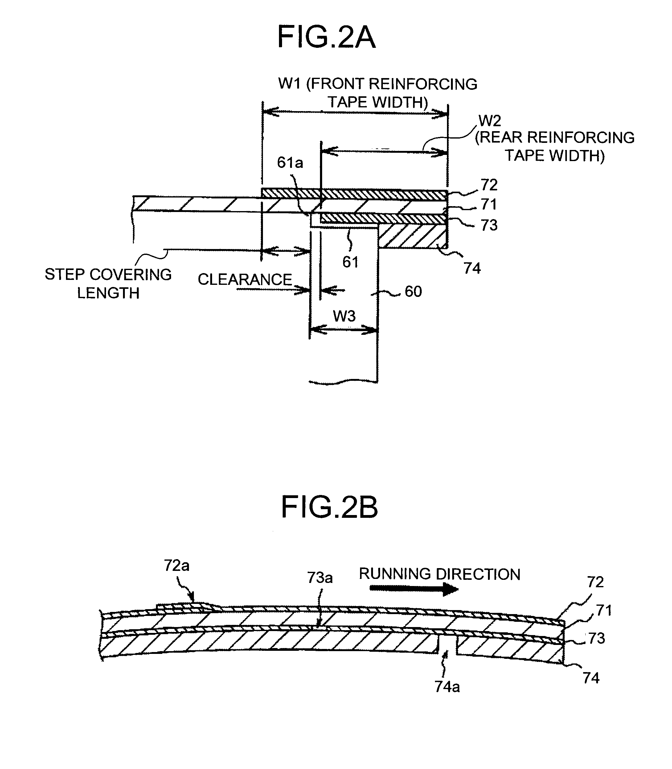
[0065]Gap between ends of a rear-side reinforcing tape in a circumferential direction: 2 millimeters

Ends of a front-side reinforcing tape in a circumferential direction: laminated with superposition of 10 millimeters in the forward direction

[0066]The width of the rear-side reinforcing tape is ensured to be 8 millimeters, and a distance between the step portion and the rear-side reinforcing tape with the guide member being bumped against the roller end is ensured to be 0.5 millimeters, thereby pr...

example 2

Intermediate transfer belt

Material: polyamide-imide

Thickness: 0.08 millimeters

[0070]Modulus of elasticity: 4800 megapascals

Intermediate transfer belt durable specifications

No crack occurred with 200K sheets

example 3

Intermediate Transfer Belt

Material: polycarbonate

Thickness: 0.15 millimeters

[0071]Modulus of elasticity: 3200 megapascals

Intermediate transfer belt durable specifications

No crack occurred with 200K sheets


PUM


Abstract

An endless belt is extended over extending rollers, and carries a toner image transferred from an image carrier or a transfer sheet. The endless belt includes a front-side reinforcing member and a rear-side reinforcing member, and a guide member for preventing meandering fixed over an approximately entire circumference on the rear-side reinforcing member. The extending rollers include a step portion provided in an end area in an axial direction facing to the rear-side reinforcing member, which has a diameter smaller than a center area in the axial direction. The front-side reinforcing member has a width wider than a width of the rear-side reinforcing member.

Description

CROSS-REFERENCE TO RELATED APPLICATIONS[0001]The present document incorporates by reference the entire contents of Japanese priority document, 2006-160211 filed in Japan on Jun. 8, 2006.BACKGROUND OF THE INVENTION[0002]1. Field of the Invention[0003]The present invention relates to a technology for forming an image through an electrophotographic process by using an intermediate transfer member formed of an endless belt, with a capability of preventing an occurrence of a crack at an edge of the endless belt and an expansion of the endless belt.[0004]2. Description of the Related Art[0005]In an electrophotographic image forming apparatus, an electrostatic latent image formed on an image carrier (photosensitive member) based on optical image information, such as document reflected light, or electric image information from a host machine is developed by using toner supplied from a developing device as a toner image, and this toner image is transferred onto a transfer sheet and then fixe...

Claims


Application Information

Patent Timeline
IPC IPC(8): G03G13/14
CPCG03G15/0131G03G2221/1642
Inventor SAWAI, YUUJI
Owner RICOH KK
Why Eureka
Try Eureka