Ink-jet printer

Active Publication Date: 2008-01-03
BROTHER KOGYO KK
View PDF7 Cites 1 Cited by
  • Summary
  • Abstract
  • Description
  • Claims
  • Application Information

AI Technical Summary

Benefits of technology

[0010]In the above-described technical background, the present invention has been developed. It is therefore an object of the present invention to solve the above-indicated problem and to be able to perform the recovery operation so as to receive ink ejected from the nozzles of the recording head even when the recording medium is fed over the position opposed to the recording head, and to easily reduce a size of the ink-jet printer.
[0013]Therefore, the present ink-jet printer can be easily downsized. Also, the waste ink receiver is positioned relative to the recording head and the medium-feed path such that the at least one waste ink receiver and the recording head are both located on one of opposite sides of the medium-feed path. Therefore, even when the recording medium is fed over a position opposed to the recording head, the recovery operation can be performed so that the waste ink receiver receives ink ejected through the nozzles of the recording head. Thus, in a case in which an image is recorded on a long recording medium in the medium-feed direction such as a roll sheet, the recovery operation can be performed when the recording head is clogged by ink during the image recording, leading to improving the quality of images recorded on each recording medium.

Problems solved by technology

According to the ink-jet printers disclosed in Patent Document 1 and 2, when the recording medium is fed above the waste ink receiver which is opposed to the recording head, the recovery operation cannot be performed.
Thus, in a case in which an image is recorded on a long recording medium in the medium-feed direction such as a roll sheet, the recovery operation cannot be performed when the recording head is clogged by ink during an image recording operation, leading to a lower quality of image recorded on a recording medium.

Method used


Image

  • Ink-jet printer
  • Ink-jet printer
  • Ink-jet printer

Examples


Embodiment Construction

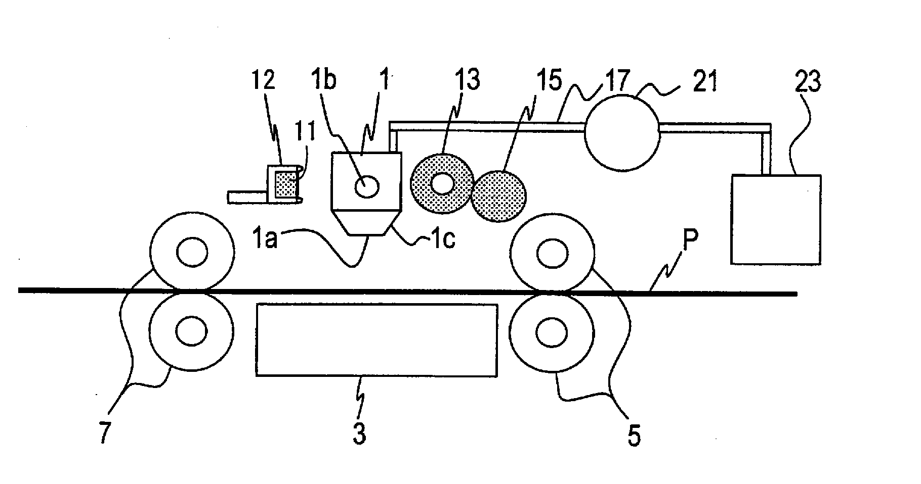
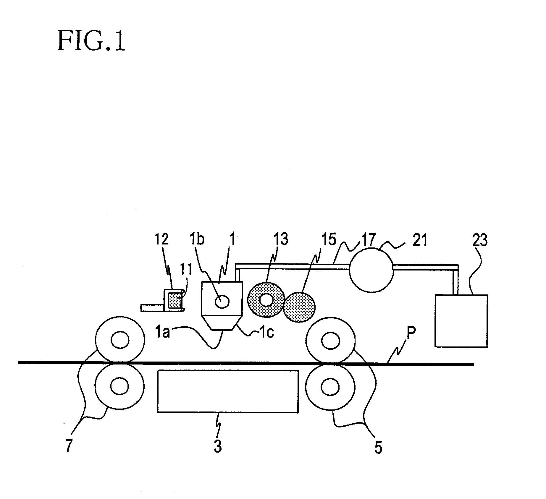
[0025]Hereinafter, there will be described preferred embodiments of the present invention by reference to the drawings. As shown in FIG. 1, an ink-jet printer, as a first embodiment of the present invention, includes a recording head 1 having a nozzle opening surface 1a and a plurality of nozzles 25c (shown in FIG. 3) which open in the nozzle opening surface 1a. The recording head 1 extends in a widthwise direction perpendicular to a sheet-feed direction as a medium-feed direction in which a recording sheet P as a recording medium is fed. The recording head 1 is operable to eject ink toward the recording sheet P through the nozzles 25c. Below the recording head 1, there is provided a platen 3 which supports the recording sheet P horizontally (flatly). In the present embodiment, the recording sheet P is described as one example of the recording medium, however, any types of recording media on which images and / or characters can be recorded by the recording head may be adopted, such as...


PUM


Abstract

An ink-jet printer including: (a) a medium feeder operable to feed a recording medium in a medium-feed direction along a medium-feed path; (b) a recording head having (b-1) a nozzle opening surface which extends in a widthwise direction perpendicular to the medium-feed direction and (b-2) a plurality of nozzles which open in the nozzle opening surface and which are arranged in the widthwise direction, the recording head being operable to eject ink toward the recording medium through the nozzles and being pivotable about a pivot axis parallel to the widthwise direction; and (c) at least one waste ink receiver configured to receive the ink ejected through the nozzles, the waste ink receiver being positioned relative to the recording head and the medium-feed path such that the at least one waste ink receiver and the recording head are both located on one of opposite sides of the medium-feed path and such that the waste ink receiver is positioned outside a locus that is described by the nozzle opening surface during pivot movement of the recording head.

Description

[0001]The present application is based on Japanese Patent Application No. 2006-181774 filed on Jun. 30, 2006, the contents of which are incorporated herein by reference.BACKGROUND OF THE INVENTION[0002]1. Field of the Invention[0003]The present invention relates to an ink-jet printer of line printer type including a medium feeder operable to feed a recording medium in a medium-feed direction and a recording head operable to eject ink toward the recording medium. In particular, the present invention relates to an ink-jet printer including a waste ink receiver configured to receive the ink ejected through nozzles of the recording head.[0004]2. Discussion of Related Art[0005]There is known an ink-jet printer of line printer type including (a) a medium feeder operable to feed a recording medium in a medium-feed direction and (b) a recording head having (b-1) a nozzle opening surface which extends in a widthwise direction perpendicular to the medium-feed direction and (b-2) a plurality o...

Claims


Application Information

Patent Timeline
IPC IPC(8): B41J2/165
CPCB41J2/16588
Inventor UMEDA, TAKAICHIRO
Owner BROTHER KOGYO KK
Why Eureka
Try Eureka