
User Interface Device

Inactive Publication Date: 2008-01-03
3DCONNEXION
View PDF10 Cites 58 Cited by
  • Summary
  • Abstract
  • Description
  • Claims
  • Application Information

AI Technical Summary

Benefits of technology

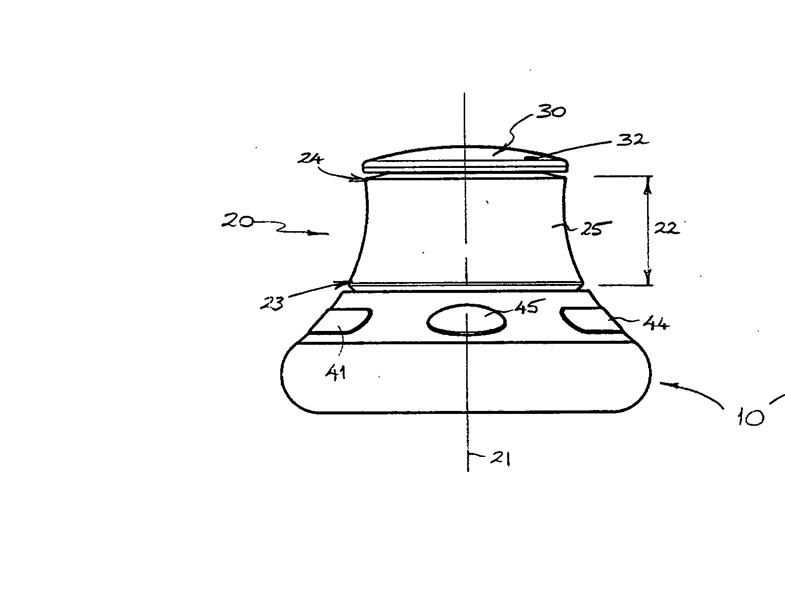
[0011] In a preferred form of the invention, the first input member has a generally circular cross-section transverse to its rotational axis, and the outer periphery of the first input member is designed to be gripped and manually rotated by the user. In this regard, the outer periphery of the first input member is preferably profiled or contoured to enhance the ergonomics of the device. For example, the outer periphery may be shaped with a curved concavity and / or provided with ribs to enhance comfort and grip.
[0025] In a preferred form of the invention, the operating software is adapted to display details of a respective control signal associated with one or more of said input members and / or the possible programmable alternatives on a display monitor associated with the computer processing unit with which the device of the invention is used. The operating software may also be adapted to display the parameters of the device such as response speed and / or sensitivity of the input members. The display may, for example, identify each input member graphically and may use keywords or phrases to identify the corresponding input control signal by its function. Such a display would clearly facilitate use of the device.
[0033] The user interface device of the invention is most particularly envisaged for applications in image or model manipulation with CAD / CAM software and image processing software. In particular, the control signals generated upon movement or actuation of the input members of the device are preferably related to free navigation of the point of view of a digital image or model, enabling both zoom and pan operations to be performed simultaneously. The configuration of the inventive device has the advantage of providing the user with a very natural and intuitive way to explore and manipulate images and designs in the computer environment.

Problems solved by technology

This positioning of the sensors makes the sensor arrangement vulnerable to knocks and shocks, and does not maximise available space.
Furthermore, these devices do not provide for an optimised ergonomic configuration.

Method used


Image

  • User Interface Device
  • User Interface Device
  • User Interface Device

Examples


Embodiment Construction

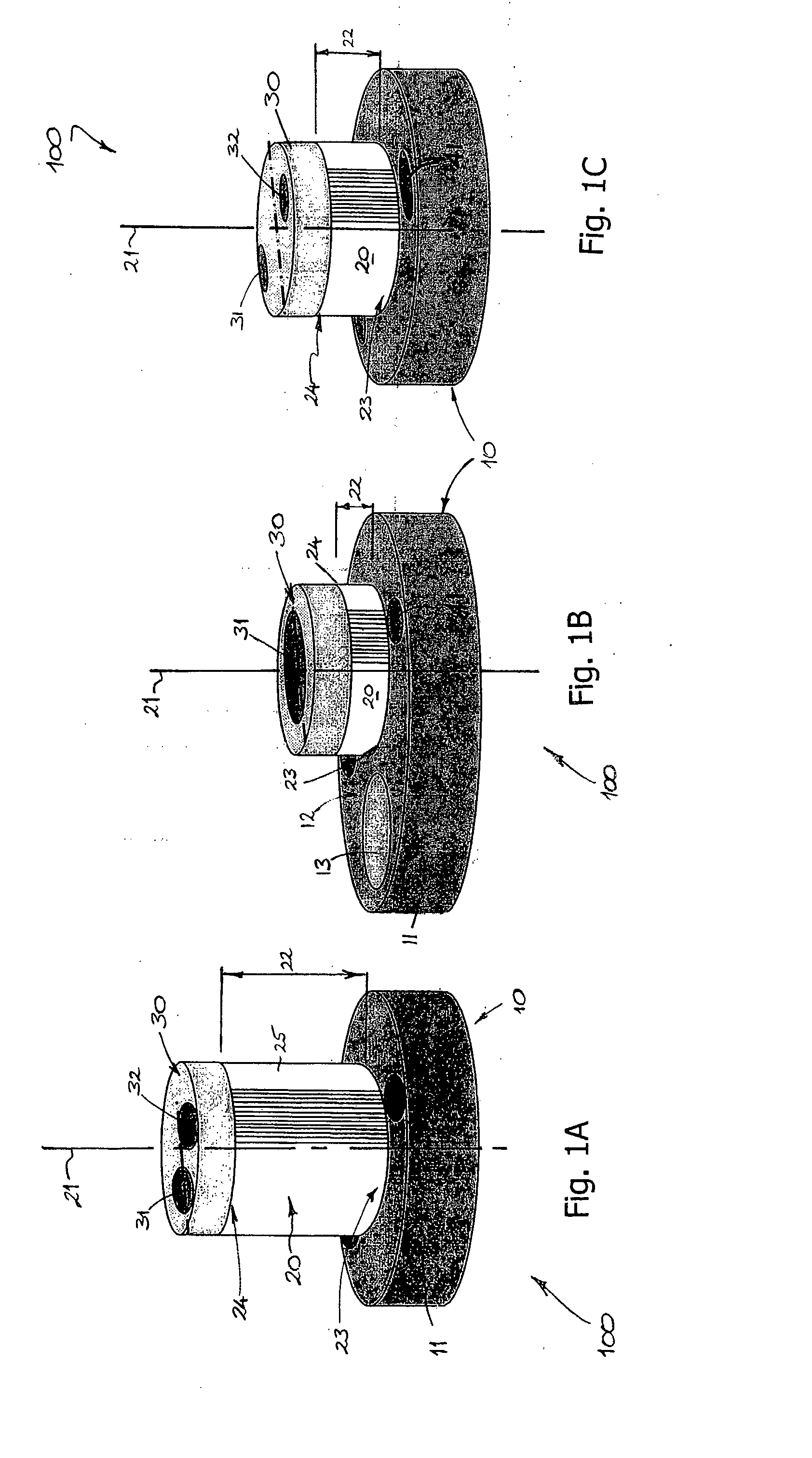
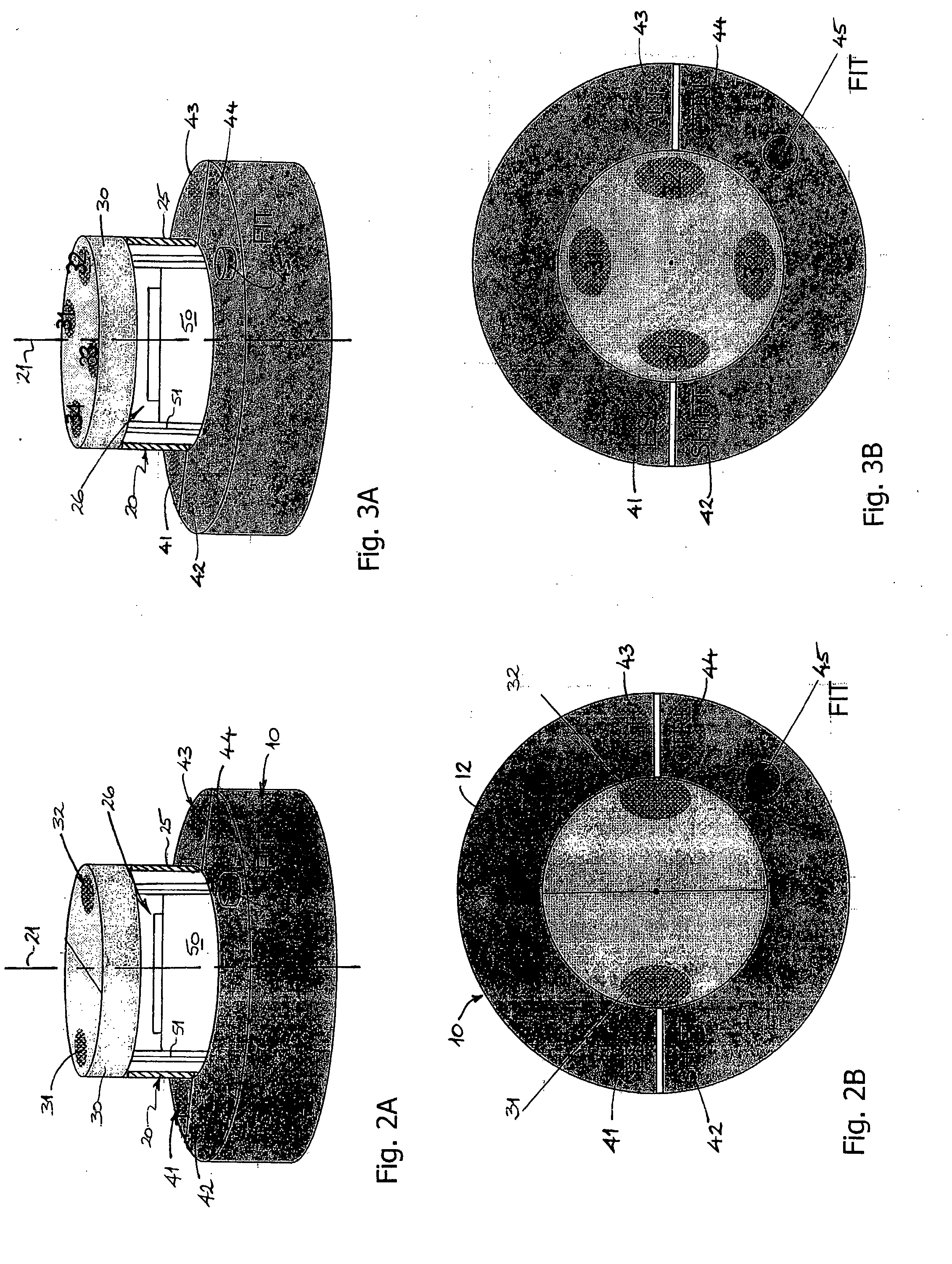
[0042] Referring firstly to FIGS. 1A to 1C, perspective views of three different examples of a user interface device (100) according to the invention are schematically illustrated. In each case, the device includes a base (10) comprising a substantially circular or oval-shaped support structure (11). The base (10) is typically robust and is designed to rest in a substantially fixed position on an operating surface, such as on a table or desktop. To this end, an underside of the base (10) may include rubber footings (not shown) for gripping the upper surface of the table or desktop. The base support structure (11) is itself also designed to at least partially house the operating electronics for the device, as will be more fully described below.

[0043] A first user input member (20) in the form of a substantially cylindrical sleeve- or ring-like element extends upwardly from and an upper side (12) of the base structure (11). This sleeve- or ring-like first input member (20) is mounted...


PUM


Abstract

The present invention provides a device (100) for manual input of control signals in a computer-related environment, the device comprising: a base (10) for supporting the device on a surface; a first input member (20) mounted on the base (10) for rotary movement about an axis (21) extending generally upwardly from the base (10), the first input member (20) having an axial extent (22) from an end region (23) proximal the base (10) to an end region (23) distal from the base and enclosing a central space (26) within which a sensor arrangement (50) is housed for detecting and interpreting rotary movement of the first input member (20) relative to the base, the first input member (20) having an opening at each of its proximal and distal end regions (23, 24); and a pair of second input members (31, 32) provided at or adjacent said distal end region (24) of the first input member (20), each of said second input members (31, 32) comprising a switch or relay adapted to be actuated by application of finger pressure. Rotary movement of the first input member (20) and / or actuation of the second input members (31, 32) is adapted to generate a corresponding control signal within the computer environment.

Description

FIELD OF THE INVENTION [0001] The present invention relates to a user interface device for a computing or computer-related environment. More particularly, the invention relates to a device with which a user may manually input control signals in a computing or a computer-related environment. [0002] The present invention has particular application as a hand-operated device which serves as a control signal input interface for a user in the manipulation and processing of digital information, such as digital images, and it will be convenient to describe the invention in this exemplary context. It will be appreciated, however, that the invention is not limited to this application, but may for example also find application in the control of a wide range of robotic and automated machinery. BACKGROUND OF THE INVENTION [0003] A broad and ever increasing range of hand-operated devices for user input of control signals in computing or digital applications are currently available in the market-p...

Claims


Application Information

Patent Timeline
IPC IPC(8): G06F3/033H01H25/06G05G1/01G05G1/10
CPCG05G1/10G05G1/01
Inventor PASCUCCI, ANTONIO
Owner 3DCONNEXION
Learn More