
Liquid crystal display device

a liquid crystal display and display device technology, applied in the field of liquid crystal display devices, can solve the problems of increasing the cost of electronic equipment, affecting the space saving of electronic equipment, and causing the so-called “moving image blur” to occur

Inactive Publication Date: 2008-01-03
KK TOSHIBA
View PDF3 Cites 10 Cited by
  • Summary
  • Abstract
  • Description
  • Claims
  • Application Information

AI Technical Summary

Problems solved by technology

In addition, when a moving image is displayed on a liquid crystal display device, a so-called “moving image blur” may occur due to the poor response of a liquid crystal.
In the conventional liquid crystal display device, however, the incorporation of both the NR circuit and the OD circuit results in the increased cost and an obstacle to space saving in the electronic apparatuses of late years.

Method used


Image

  • Liquid crystal display device
  • Liquid crystal display device
  • Liquid crystal display device

Examples


Embodiment Construction

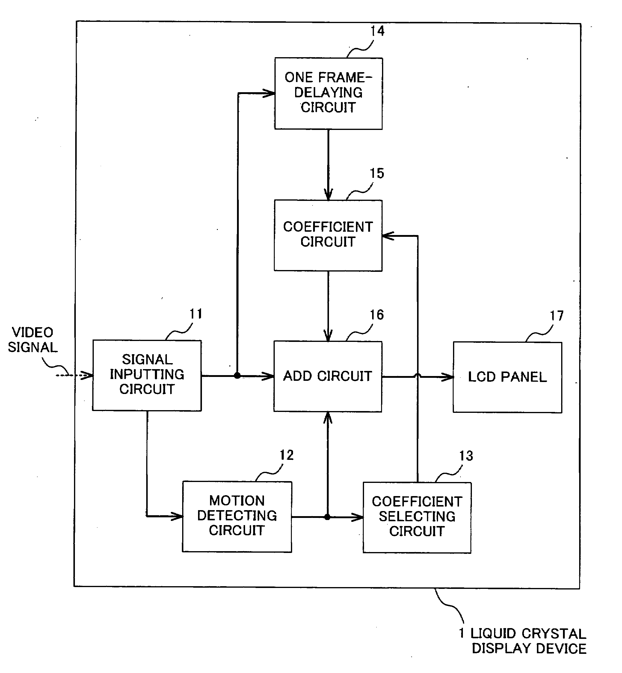
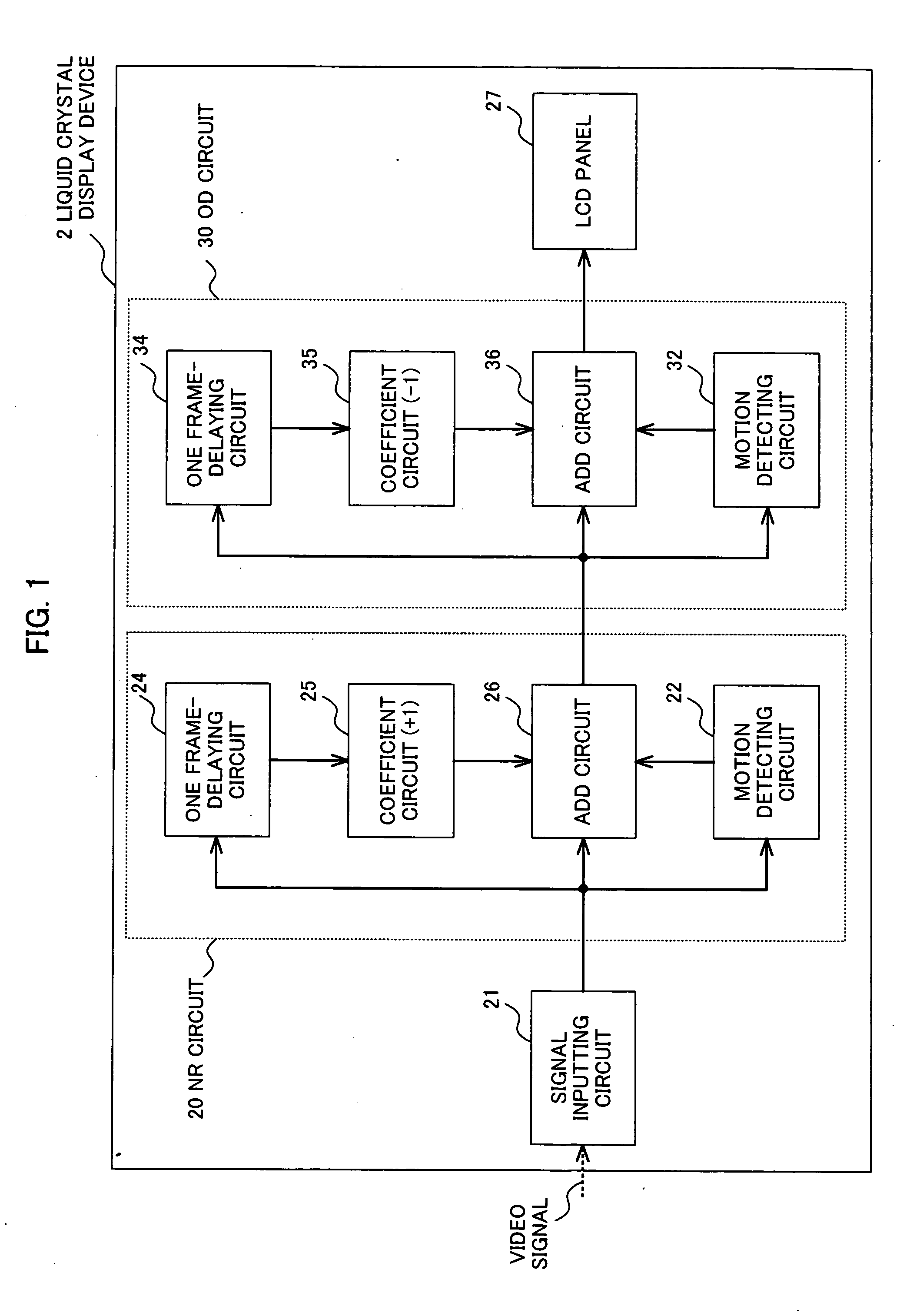
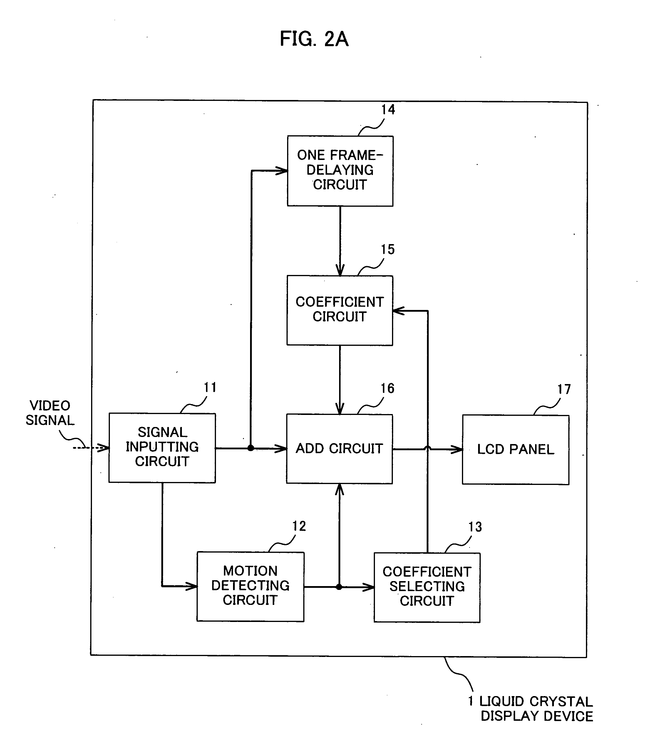
[0018]Various embodiments according to the invention will be described hereinafter with reference to the accompanying drawings. In general, according to one embodiment of the invention, there is provided a liquid crystal display device, including: a receiving portion for receiving a video signal; a motion detecting portion for detecting whether an image corresponding to the video signal is a still image or a moving image; and a signal adding portion for, when the motion detecting portion detects that the image is the still image, operating as a noise reduction circuit for the image, and when the motion detecting portion detects that the image is the moving image, operating as an overdrive circuit for the image.

[0019]In addition, according to the embodiment of the invention, there is provided a liquid crystal display device, including: a receiving portion for receiving a video signal; a motion detecting portion for detecting whether an image corresponding to the video signal is a sti...


PUM

PropertyMeasurementUnit
mean voltageaaaaaaaaaa
sizeaaaaaaaaaa
ODaaaaaaaaaa

Abstract

A liquid crystal display device (1) according to the invention adds a former image and a latter image which are continuous. When an image corresponding to a received video signal is a still image, an effect of noise reduction is provided by multiplying the former image by a positive coefficient. On the other hand, when an image corresponding to the received video signal is a moving image, a difference between the former image and the latter image is obtained by multiplying the former image by a negative coefficient, thereby providing an effect of overdrive.

Description

[0001]The present application is based on Japanese application No. 2006-180267, the entire contents of which are incorporated herein by reference.BACKGROUND[0002]1. Field[0003]One embodiment of the invention relates to a liquid crystal display device, and more particularly to a liquid crystal display device which is capable of exhibiting an effect of overdrive in a noise reduction circuit.[0004]2. Description of the Related Art[0005]In recent years, scale-up of image display apparatuses such as a television has progressed, and thus general consumers have been concerned about animage quality as well about which they have not been nervous so much for image display apparatuses each having a conventional size.[0006]When a still image is displayed, a flicker occurs in an image in which any flicker should not essentially occur due to addition of a noise to a video signal in some cases. In order to dissolve such a state, there has been developed an image display apparatus which has a noise...

Claims


Application Information

Patent Timeline
Patent Type & Authority Applications(United States)
IPC IPC(8): G09G3/36G02F1/133G09G3/20H04N5/21H04N5/66
CPCG09G3/3611G09G2320/0252G09G2340/16G09G2320/106G09G2320/0261
Inventor ABE, HIROTOSHI
Owner KK TOSHIBA
Learn More