
Ultrasonic inspection and repair mode selection

a technology of ultrasonic inspection and repair mode, applied in the direction of instruments, specific gravity measurement, measurement devices, etc., can solve the problems of difficult to set up and use, time-consuming and physically challenging activities, and laborious manual scanning of structures, etc., and achieves cost-effective and easy-to-use components and control systems. , the difficulty of obtaining data for such images

Active Publication Date: 2008-01-03
THE BOEING CO
View PDF30 Cites 57 Cited by
  • Summary
  • Abstract
  • Description
  • Claims
  • Application Information

AI Technical Summary

Benefits of technology

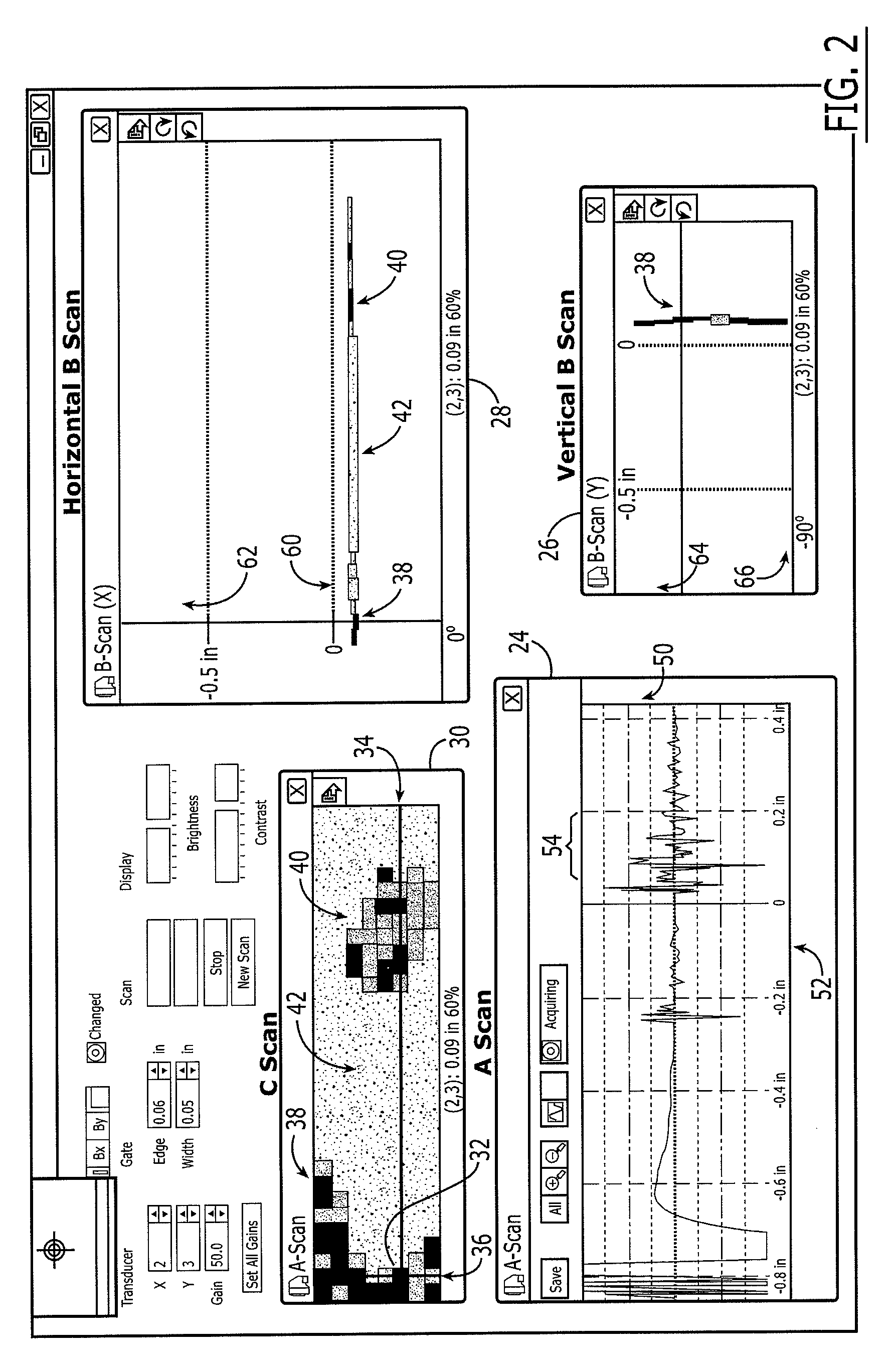
The invention relates to a method of inspecting an aircraft structure using a two-dimensional array of sensors. The method involves sending ultrasonic pulses into the surface of the structure, receiving echo signals, and displaying an image of any damage within the structure. The method also includes determining whether the damage satisfies a predetermined criterion and selecting a mode of returning the structure to flying service based on the determination. The predetermined criterion may include a linear dimension or a depth / area, and the method may involve displaying the damage using an echo amplitude C-scan image, a depth C-scan image, or a B-scan image. The invention also includes making repairs to the damage and permitting vehicle traffic to pass over or under the structure. The technical effects of the invention include improved inspection of aircraft structures and reduced downtime for repairs.

Problems solved by technology

Inspections may also be prompted by incidents such as collisions and ballistic impacts that are suspected or known to cause damages.
Thus, collecting data for such images can be time-consuming and physically challenging activities.
Thus, manual scanning of structures is time-consuming, labor-intensive, and prone to human error.
Thus, typical AUSS systems include robotic components and control systems that can be expensive to obtain and challenging to set up and use for any given inspection.

Method used


Image

  • Ultrasonic inspection and repair mode selection
  • Ultrasonic inspection and repair mode selection
  • Ultrasonic inspection and repair mode selection

Examples


Embodiment Construction

[0036]The present invention now will be described more fully hereinafter with reference to the accompanying drawings, in which some, but not all embodiments of the invention are shown. Indeed, the invention may be embodied in many different forms and should not be construed as limited to the embodiments set forth herein; rather, these embodiments are provided so that this disclosure will satisfy applicable legal requirements. Like numbers refer to like elements throughout.

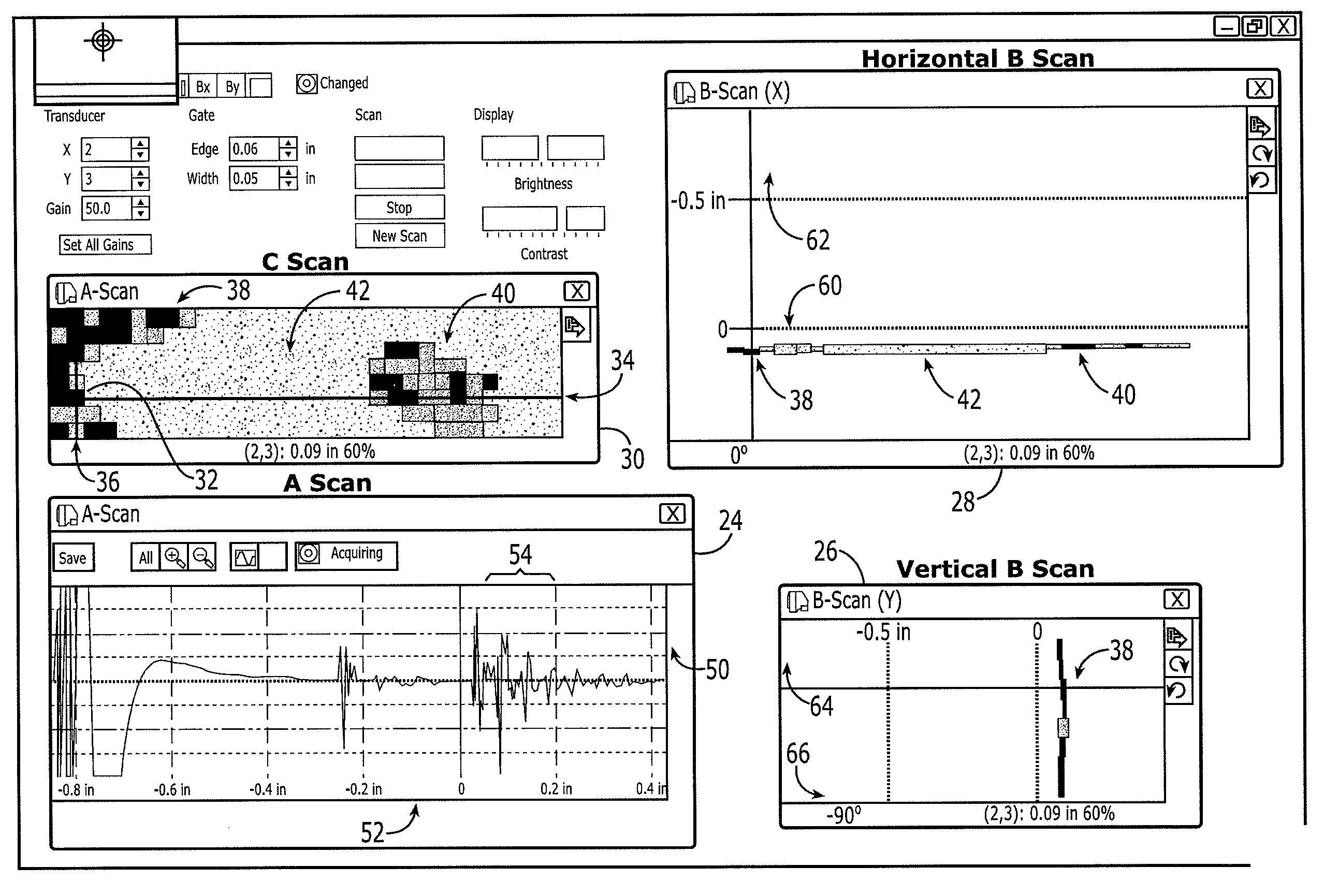
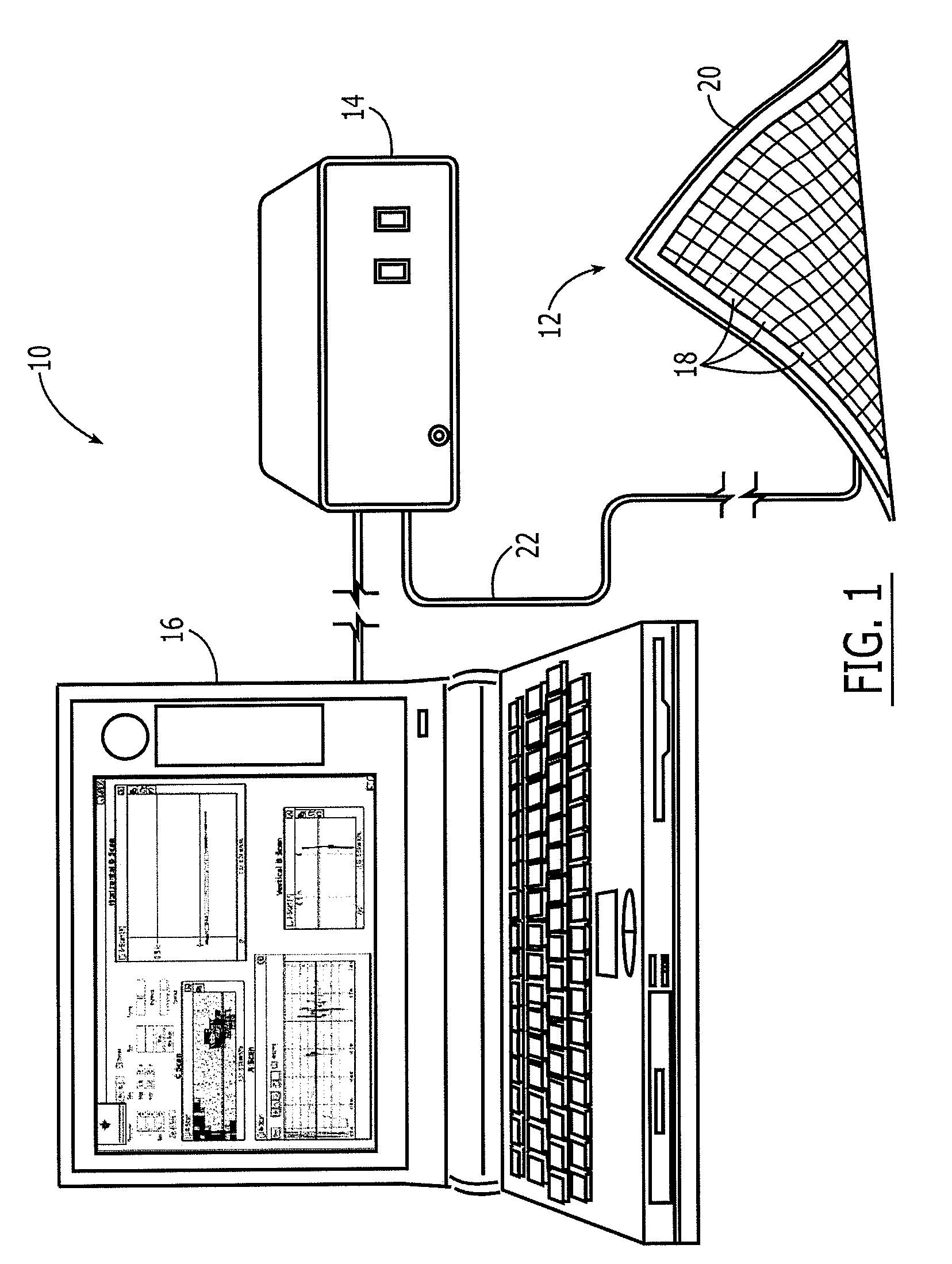
[0037]An ultrasonic inspection system 10 by which a structure, such as an aircraft structure or component, may be inspected according to at least one embodiment of the present invention is shown in FIG. 1. The ultrasonic inspection system 10 includes a flexible sensor array 12, an array controller 14, and a computing and display device 16. The flexible sensor array 12 comprises ultrasonic sensors 18 bonded to a flexible mat 20 in a regularly spaced pattern. Each ultrasonic sensor comprises a transducer element that...


PUM

PropertyMeasurementUnit
ultrasonic echoaaaaaaaaaa
linear dimensionaaaaaaaaaa
lengthaaaaaaaaaa

Abstract

In a method of inspecting a structure, a two-dimensional array of sensors is disposed onto a surface, ultrasonic pulses are sent into the surface, and echo signals are received. An image of damage within the structure is graphically displayed, a determination of whether the damage satisfies a predetermined criterion is made, and a mode of returning the structure to usage or service is selected. The predetermined criterion may define a length, a depth, and an area. A-scan, B-scan, and C-scan images of the damage may be displayed. Threshold images may be displayed wherein each pixel of a matrix of pixels is colored one of only two colors.

Description

FIELD OF THE INVENTION[0001]Embodiments of the present invention relate generally to methods for inspecting structures. More particularly, embodiments of the invention relate to methods for determining whether damage satisfies criteria for different levels of repair, and selecting modes of returning a structure to usage.BACKGROUND OF THE INVENTION[0002]Non-destructive inspection (NDI) of structures involves examining a structure without harming the structure or requiring significant disassembly. Non-destructive inspection is typically preferred to avoid the time and costs associated with the removal of a part for inspection and to avoid the potential for causing damages when inspection is needed. Non-destructive inspection is used in the aircraft industry to inspect aircraft structures such as composite structures and bonded panels. Inspections may identify defects such as cracks, discontinuities, disbonds between layers, voids, and areas having undesirable porosity. Preventive insp...

Claims


Application Information

Patent Timeline
Patent Type & Authority Applications(United States)
IPC IPC(8): G01N29/04
CPCG01N29/0645G01N29/223G01N2291/2694G01N2291/106G01N2291/044
Inventor GEORGESON, GARY E.
Owner THE BOEING CO
Learn More