
Patient programmer for implantable devices

a patient programmer and implantable device technology, applied in the field of powered, implantable medical systems, can solve the problems of insufficient internal volume of the implantable device, inability to recharge the primary battery, and inability to meet the needs of patients,

Active Publication Date: 2007-12-20
BOSTON SCI NEUROMODULATION CORP
View PDF31 Cites 161 Cited by
  • Summary
  • Abstract
  • Description
  • Claims
  • Application Information

AI Technical Summary

Problems solved by technology

Energy intensive applications, e.g., ones employing a stimulator having many stimulation channels can quickly deplete the battery and require that the stimulator be explanted after only a short implant period.
Nevertheless, even a rechargeable battery has a finite life, as the battery can only be recharged so many times before reaching its end of useful life.
While battery design and capacity have improved greatly, despite those advances, the physical bulk of a primary battery can take up more than half the total internal volume of an implantable device.
Consequently, for energy intensive applications, the primary battery employed is generally large and therefore any device containing such a battery is necessarily also large.
A disadvantage, however, of an implantable system having a replenishable power source such as a rechargeable battery is that the user must recharge the battery regularly as it becomes depleted of charge.
Such a requirement to recharge the battery can be problematic because it requires patient compliance to timely recharge the battery and, in addition, the patient must be alerted when the battery requires recharging.

Method used


Image

  • Patient programmer for implantable devices
  • Patient programmer for implantable devices
  • Patient programmer for implantable devices

Examples


Embodiment Construction

[0049] The following description is of the best mode presently contemplated for carrying out the invention. This description is not to be taken in a limiting sense, but is made merely for the purpose of describing the general principles of the invention. The scope of the invention should be determined with reference to the claims.

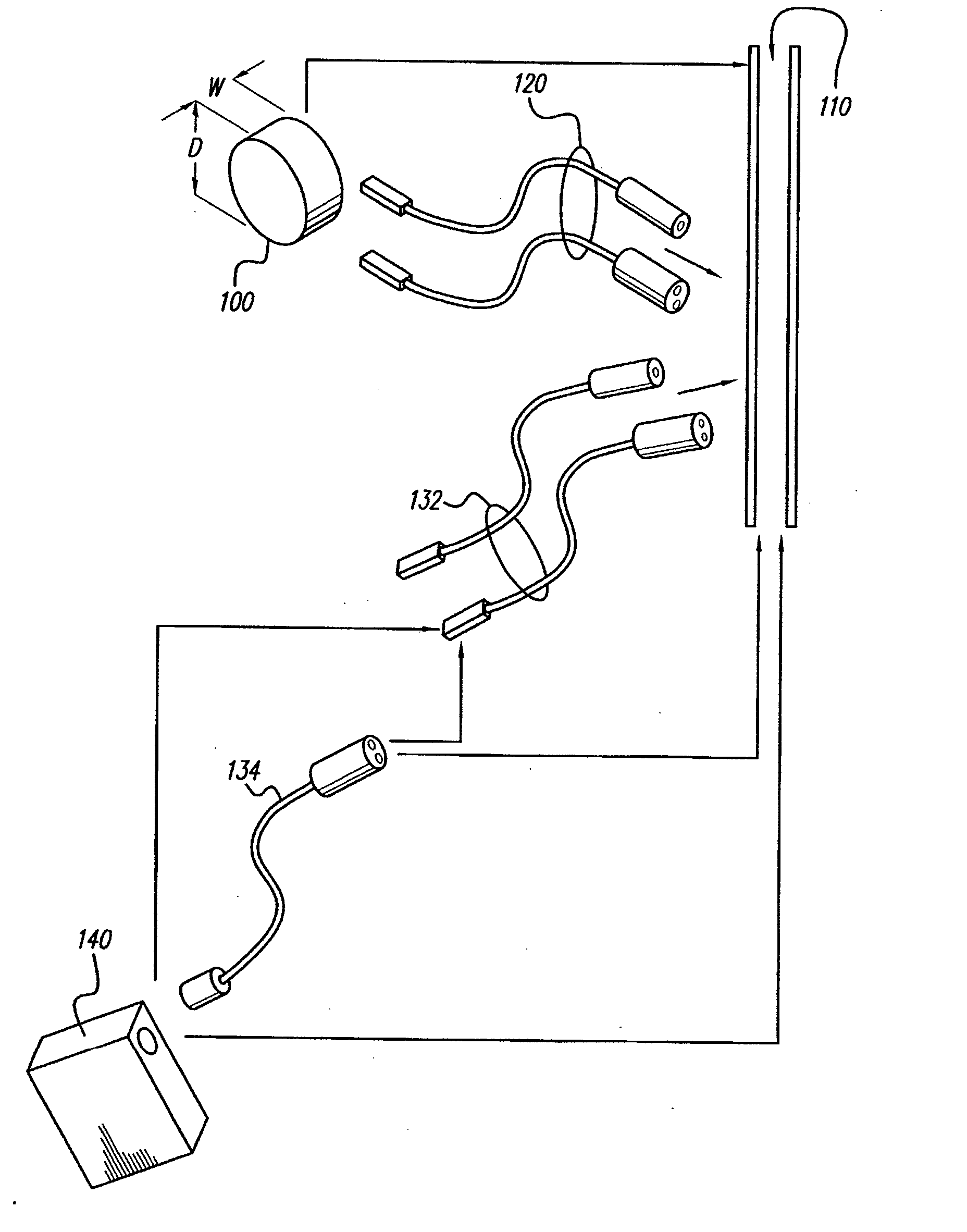
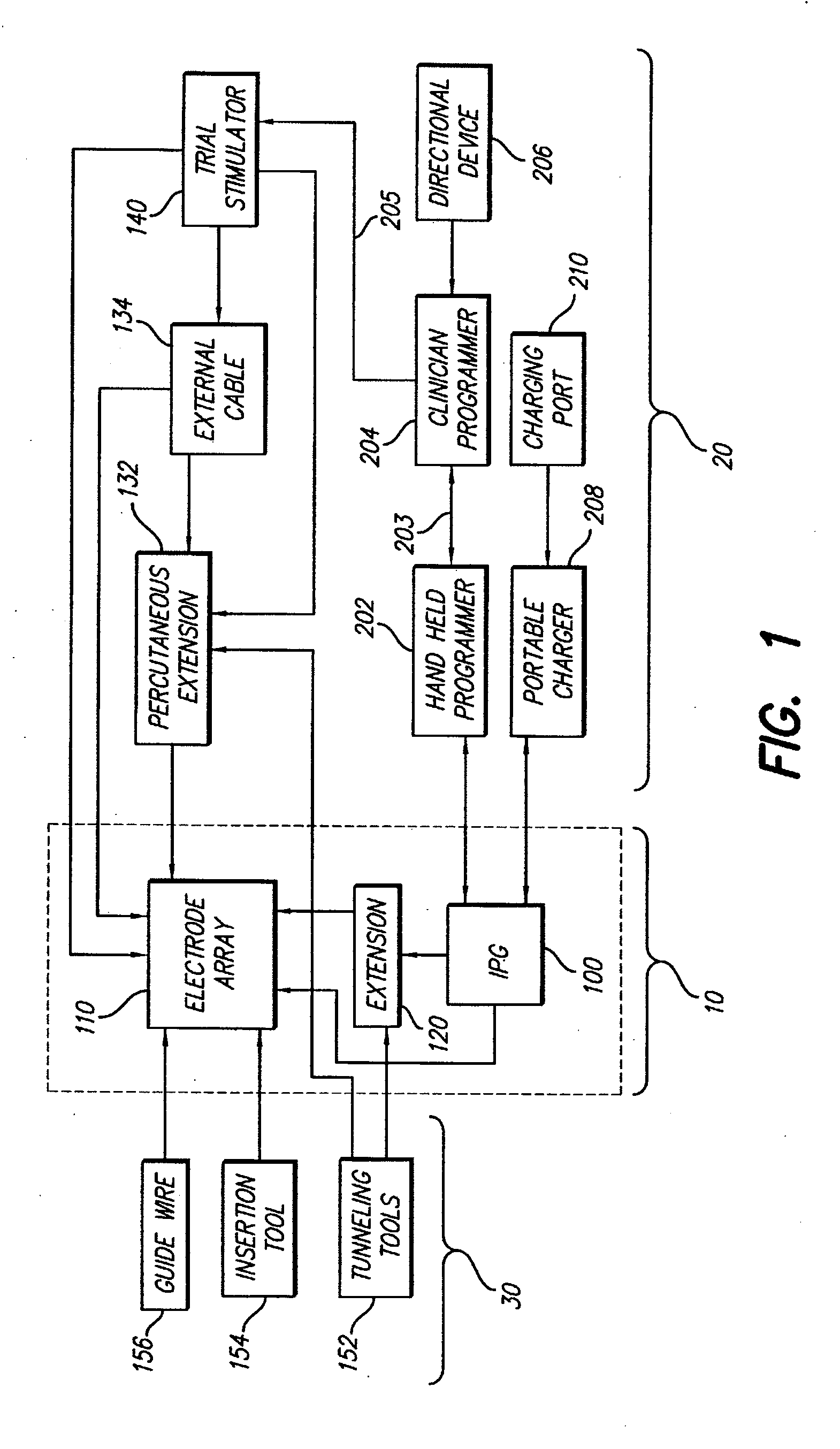
[0050] Turning first to FIG. 1, there is shown a block diagram that illustrates the various components of a spinal cord stimulation (SCS) system. These components may be subdivided into three broad categories: (1) implantable components 10, (2) external components 20, and (3) surgical components 30. As seen in FIG. 1, the implantable components 10 include an implantable pulse generator (IPG) 100, an electrode array 110, and (as needed) an extension 120. The extension 120 is used to electrically connect the electrode array 110 to the IPG 100. In a preferred embodiment, the IPG 100, described more fully below in connection with FIGS. 4A, 4B and 4C, comprises...


PUM


Abstract

The invention is a system and method for detecting the status of a rechargeable battery included within an implantable medical device. The medical device can incorporate a status indicator which signals the user concerning the battery status, e.g., low battery level. The signal may be audible or it may arise from an electrical stimulation that is perceptually distinguished from the operative, therapeutic stimulation. The external programmer may also incorporate a second battery status indicator that is visual, audible, or physically felt. Battery status data may be conveyed on visual displays on the external programmer by uploading this information from the medical device using a bidirectional telemetry link. Such battery status data are helpful to the user to indicate when the battery should be recharged and to the clinician to monitor patient compliance and to determine end-of-useful life of the rechargeable battery.

Description

[0001] This application is a continuation of co-pending U.S. application Ser. No. 10 / 356,414, filed Jan. 31, 2003, which is a continuation-in-part of U.S. application Ser. No. 09 / 626,010, filed Jul. 26, 2000, which application claims the benefit of U.S. Provisional Application Ser. No. 60 / 145,829, filed Jul. 27, 1999, the disclosure of which is hereby incorporated by reference.[0002] The present invention relates to powered, implantable medical device systems having a replenishable power source, such as a rechargeable battery, and status indicators for indicating the status of the replenishable power source or rechargeable battery. BACKGROUND OF THE INVENTION [0003] There are many kinds of powered, implantable medical systems, e.g., stimulating systems for spinal cord stimulation for pain management, stimulators for controlling urinary incontinence, deep brain stimulators for treating brain disorders such as Parkinson's Disease, and cochlear stimulators for restoring hearing to the ...

Claims


Application Information

Patent Timeline
Patent Type & Authority Applications(United States)
IPC IPC(8): A61N1/02A61N1/05A61N1/34A61N1/36A61N1/372A61N1/378
CPCA61N1/36071A61N1/36185A61N1/37241A61N1/0553A61N1/37252A61N1/3787A61N1/37247A61N1/0551A61N1/37235
Inventor WOODS, CARLA MANNTHACKER, JAMES R.PETERSON, DAVID K.L.
Owner BOSTON SCI NEUROMODULATION CORP
Learn More