
Feel presenting device and method

a technology of tactile feedback and display device, which is applied in the field of tactile feedback device and method, can solve the problems of poor portability of most existing haptic display, complex configuration, and complex tactile display, and achieve the effect of improving expressive power

Inactive Publication Date: 2007-12-20
CANON KK
View PDF9 Cites 54 Cited by
  • Summary
  • Abstract
  • Description
  • Claims
  • Application Information

AI Technical Summary

Benefits of technology

[0017]The present invention provides a tactile-feedback device whose expressive power is improved, such as allowing a user to perceive a plane or an object surface even using a stimulation unit having a simple configuration such as a vibration motor. This is realized through the following arrangements.

Problems solved by technology

However, most of the existing haptic displays are poor in portability, and also have a complex configuration, and tend to be expensive.
Also, tactile displays tend to be complex in configuration, and also with the current technology, it is difficult to present the feel of an object to a user sufficiently.
With the above-mentioned existing techniques, vibration motors are employed, so the contact with the virtual object can be readily taught to the user, but it has been difficult to present the user with information other than that.
On the other hand, vibration motors serving as simple actuators cannot perform a fine perceptual expression sufficiently.
However, with this method, allowing a user to perceive the material of each wall has not yet been completely successful.
As described above, vibration motors are small, inexpensive, and lightweight, so it has been possible to present the contact with a virtual object by installing the vibration motors in arbitrary portions, but it has been difficult to perform various types of expression other than the contact information.
Particularly, it has been difficult to allow a user to perceive a plane or an object surface.

Method used


Image

  • Feel presenting device and method
  • Feel presenting device and method
  • Feel presenting device and method

Examples


first embodiment

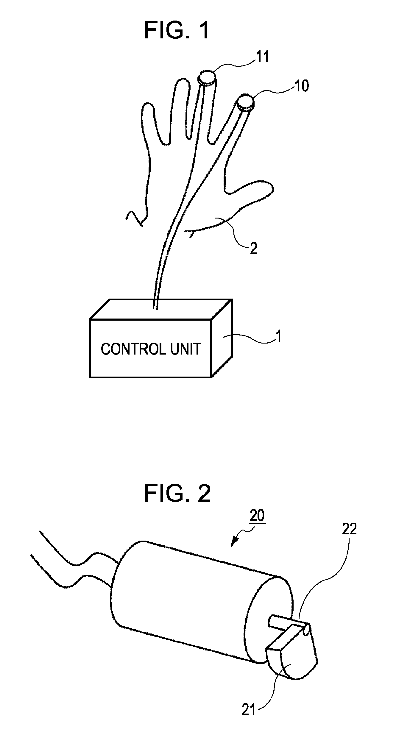
[0042]FIG. 1 is a diagram illustrating the configuration of a tactile-feedback device according to a first embodiment of the present invention. The tactile-feedback device shown in FIG. 1 comprises two vibration motors 10 and 11 serving as stimulation units, and a control unit 1 configured to control the operation of the vibration motors 10 and 11. In FIG. 1, an example is illustrated wherein the vibration motors 10 and 11 are put on fingertips, but the vibration motors may be put on any portion of a human body as long as the two vibration motors can be disposed in the same neighborhood to some extent.

[0043]The vibration motors are each put on a human body such that the revolution direction of the eccentric rotor is parallel to a skin surface of the human body. Also, though not particularly shown in FIG. 1, there are provided wearing portions configured to allow a user to wear the vibration motors on fingertips. The wearing portions are, for example, made up of an arrangement which ...

second embodiment

[0077]With the first embodiment, an example including the two stimulation units has been shown, but the number of stimulation units may be greater than two. For example, FIG. 11 illustrates an example in the case of wearing coin-type vibration motors 10 to 13 serving as stimulation units on four fingers.

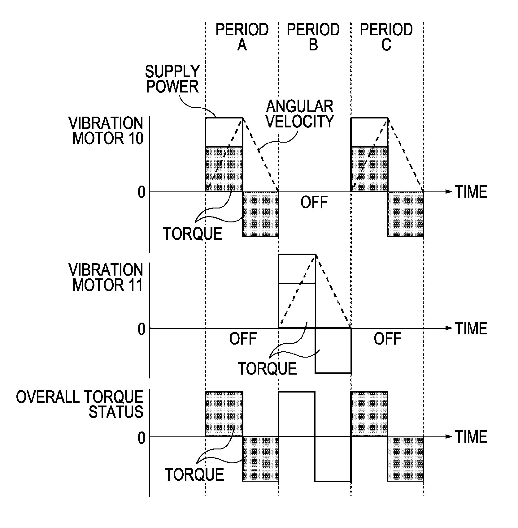
[0078]Hereafter, a state in which a stimulation unit generates force that a human body can perceive will be referred to as an ON state, and a state in which a stimulation unit generates no force that a human body can perceive will be referred to as an OFF state.

[0079]Particularly, in the event of employing a vibration motor as a stimulation unit, a state in which torque is generated by the acceleration and deceleration of the eccentric rotor, and force that a human body can perceive is generated parallel to a skin surface will be referred to as an ON state. Also, a state in which torque is not generated by the acceleration and deceleration of the eccentric rotor, and force that a hum...

third embodiment

[0089]With the perceptual presentation of the present invention, a display can be employed on which a virtual object is displayed, besides the vibration motors. As for the display, a liquid crystal, plasma, CRT, projector, head mount display (HMD), and so forth may be employed.

[0090]Also, the feel of touching an object surface may be presented depending on the relation between an actual human body position and a virtual object position together with a method arranged to detect a human body position. As for a detection method of a human body position, methods may be employed such as a method employing markers and a camera, a method arranged to determine a human body shape using image processing, a technique employing a magnetic sensor, acceleration and angular velocity sensor, magnetic sensor, or the like.

[0091]FIG. 15 illustrates a tactile-feedback device made up of a head mount display 100 as a display, and a method employing markers 108 and a camera 109 as a position-detection met...


PUM


Abstract

The present invention provides a device configured to present the feel of a plane or an object surface to a user using equipment configured to generate physical vibration such as a vibration motor or the like. A plurality of vibration motors including an eccentric rotor are put on a human body, and torque generated at the vibration motor along with an angular velocity fluctuation is provided to a skin surface in the horizontal direction with a different timing. Alternately generating torque by the plurality of vibration motors enables the user to perceive a plane or an object surface.

Description

BACKGROUND OF THE INVENTION[0001]1. Field of the Invention[0002]The present invention relates to a tactile-feedback device and method, and particularly relates to a tactile-feedback device and method configured to allow a user to perceive contact with a virtual object in the field of virtual reality.[0003]2. Description of the Related Art[0004]Within the technology field of presenting virtual reality to a user, the study of a tactile display configured to allow a user to touch a virtual object, or to operate a virtual object has been performed.[0005]What is generally referred to as “tactile displays” in the broad sense are classified into “haptic displays” (force feedback displays) configured to present reaction force from an object to a human body, and “tactile displays” in the narrower sense configured to present the feel of an object. However, most of the existing haptic displays are poor in portability, and also have a complex configuration, and tend to be expensive. Also, tacti...

Claims


Application Information

Patent Timeline
Patent Type & Authority Applications(United States)
IPC IPC(8): G09G5/00
CPCG06F3/016
Inventor NOGAMI, ATSUSHINISHIMURA, NAOKITOKITA, TOSHINOBUIWASE, YOSHIHIKO
Owner CANON KK
Learn More