Level shift circuit and method for the same
a level shift circuit and level shift technology, applied in logic circuits, pulse automatic control, pulse technique, etc., can solve the problem of even longer time delay, and achieve the effect of speeding up output voltage level switching
- Summary
- Abstract
- Description
- Claims
- Application Information
AI Technical Summary
Benefits of technology
Problems solved by technology
Method used
Image
Examples
Embodiment Construction
[0029]For purpose of simplicity, in all of the following embodiments, it is assumed that the first operational voltage is 5V and the second operational voltage VP2 is 23V. However, the present invention should not be limited to such arrangement, but may be applied to level shift between any two voltage levels.
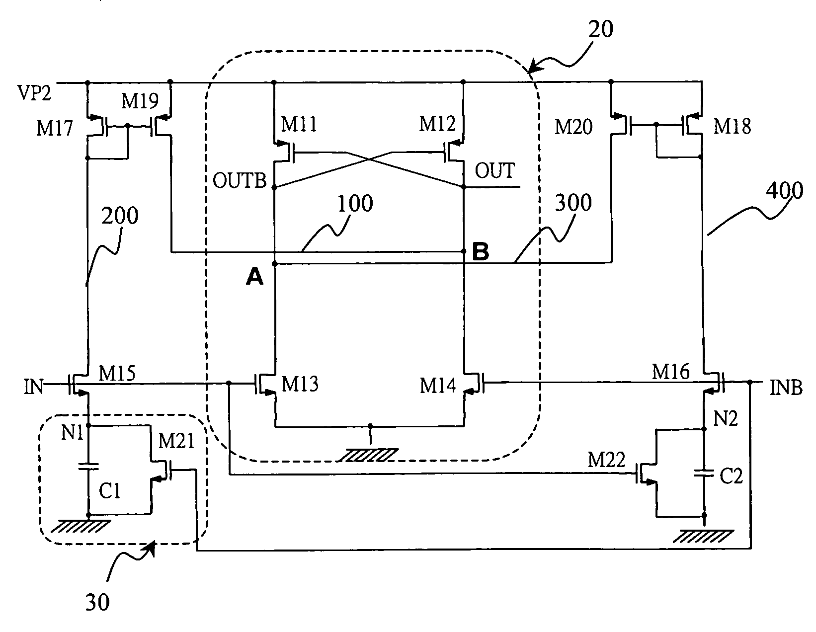
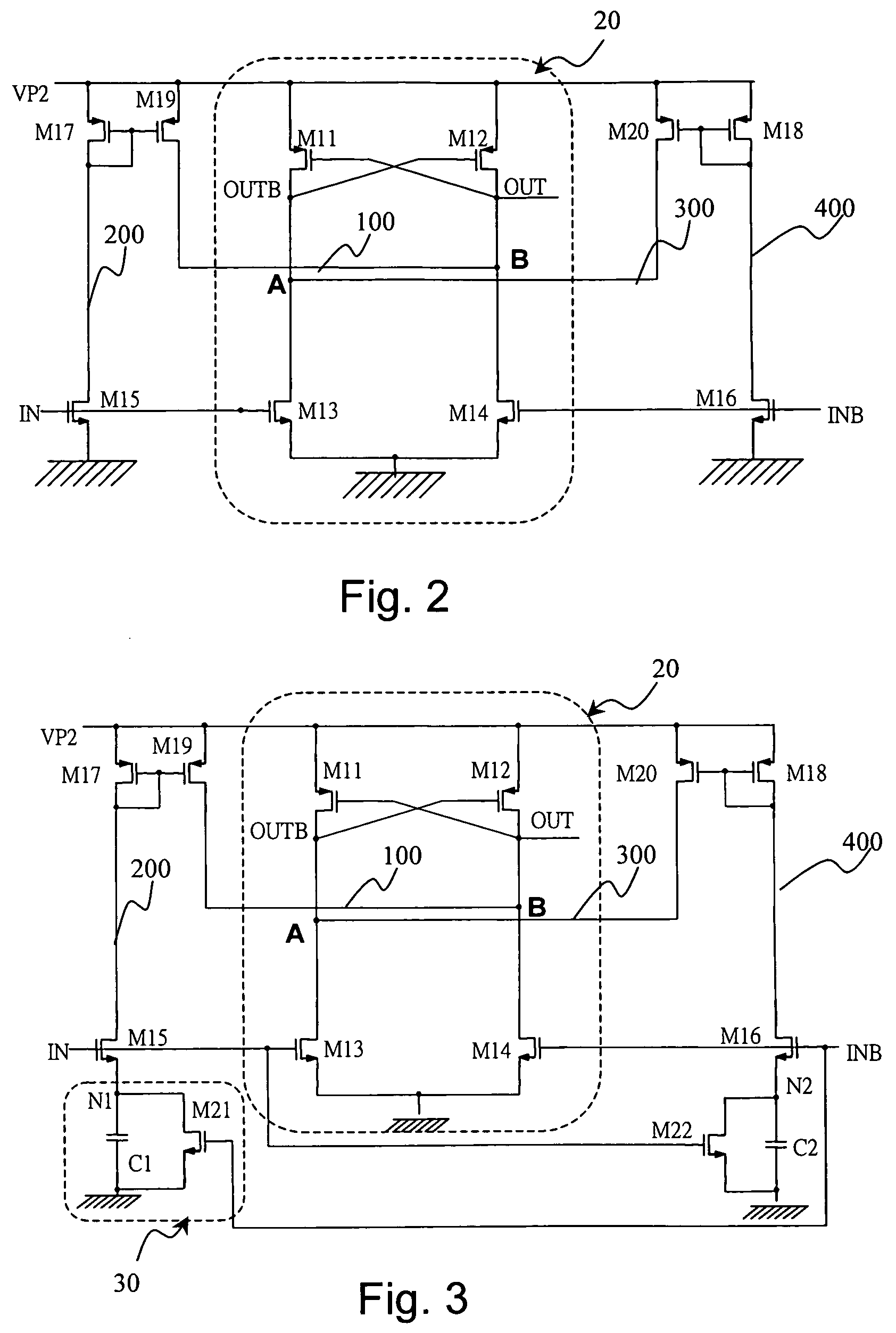
[0030]FIG. 2 schematically shows a first preferred embodiment according to the present invention. As shown in the figure, a level shift circuit comprises a pair of PMOS transistors M11 and M12, and a pair of NMOS transistors M13 and M14 (the PMOS and NMOS pairs constituting basic level shift means 20). In addition to the above, the level shift circuit according to this embodiment further comprises a current path 100 (VP2-M19-node B) which is connected to the source for supplying the second operational voltage VP2. The current path serves to pull high the voltage level at the node B, as explained below.
[0031]More specifically, referring to FIG. 2, when the input IN switches from...
PUM
 Abstract
Description
Claims
Application Information
 - R&D
- Intellectual Property
- Life Sciences
- Materials
- Tech Scout
- Unparalleled Data Quality
- Higher Quality Content
- 60% Fewer Hallucinations
Browse by: Latest US Patents, China's latest patents, Technical Efficacy Thesaurus, Application Domain, Technology Topic, Popular Technical Reports.
© 2025 PatSnap. All rights reserved.Legal|Privacy policy|Modern Slavery Act Transparency Statement|Sitemap|About US| Contact US: help@patsnap.com


