
Engine output control apparatus of power train

a technology of engine output control and power train, which is applied in the direction of machines/engines, instruments, etc., can solve the problems of low engine output control responsiveness of the system, and achieve the effect of reducing the magnitude of engine torque, enhancing the shift response, and high engine output control responsiveness

Active Publication Date: 2007-12-13
NISSAN MOTOR CO LTD +1
View PDF3 Cites 13 Cited by
  • Summary
  • Abstract
  • Description
  • Claims
  • Application Information

AI Technical Summary

Benefits of technology

[0012]To remarkably enhance the shift response, it is considered to use ignition timing control having a relatively high engine-output-control responsiveness rather than throttle opening control. On the one hand, there is a general relationship between ignition timing and engine output torque, as shown in FIG. 13. The peak of the ignition-timing versus engine-torque characteristic curve of FIG. 13 indicates the basic ignition timing, that is, the minimum advance of best torque, generally abbreviated to “MBT”. The magnitude of engine torque tends to reduce in accordance with an increase in an ignition timing retard rate from the “MBT” point. Therefore, engine output control (engine torque limiting action) can be attained by ignition timing change (ignition timing retard). As is generally known, in comparison with engine output control executed by the throttle opening control system (hereinafter is referred to as “throttle-opening-control based engine output control”), engine output control executed by the ignition timing control system (hereinafter is referred to as “ignition-timing-control based engine output control”) is superior in engine-output-control responsiveness.

Problems solved by technology

However, the engine output control device disclosed in JP2004-092522, has the following drawbacks, since engine output limiting action is made by electronically controlling a throttle-opening decrease and the throttle opening control system has a low engine-output-control responsiveness.

Method used


Image

  • Engine output control apparatus of power train
  • Engine output control apparatus of power train
  • Engine output control apparatus of power train

Examples


Embodiment Construction

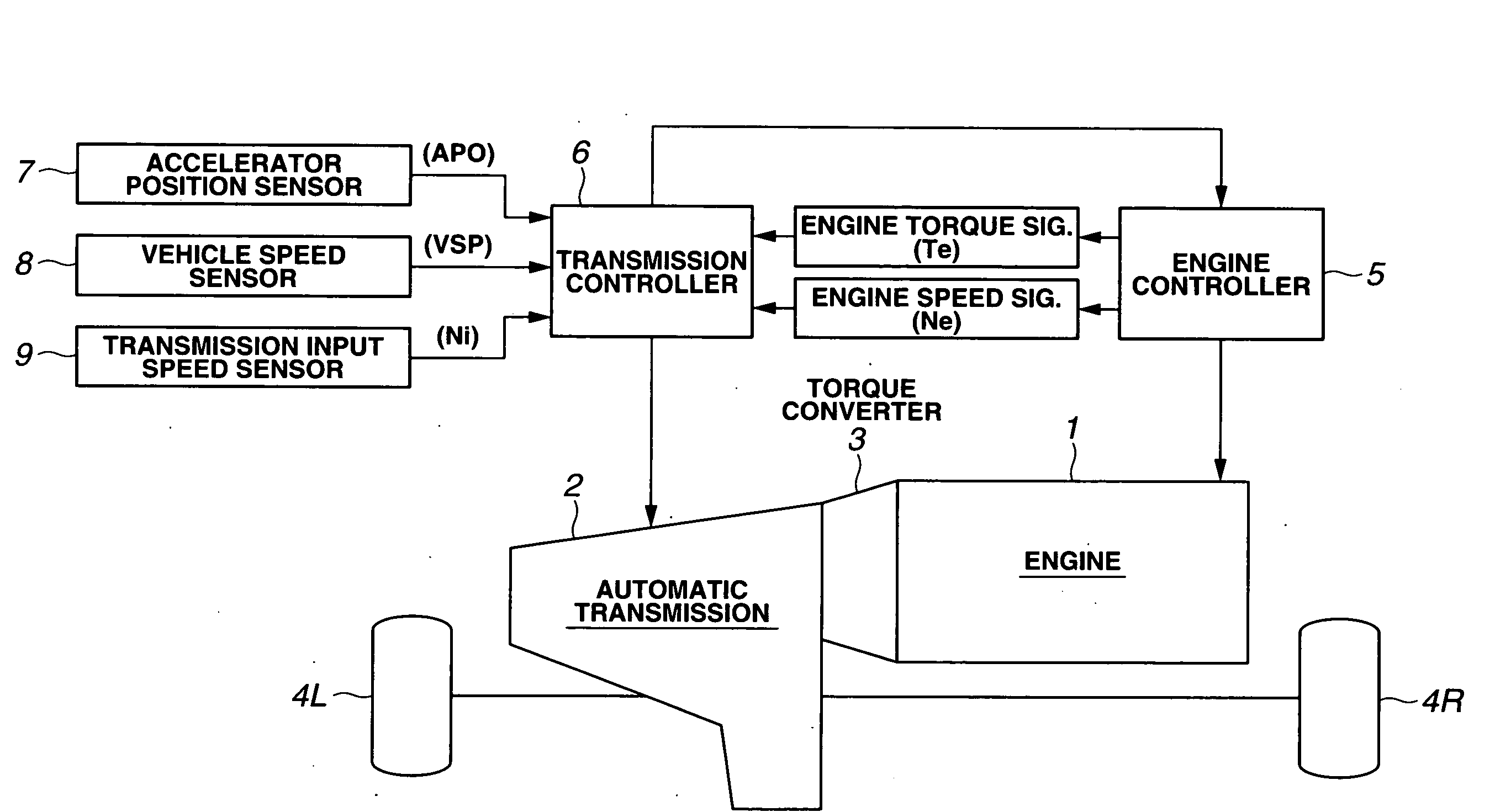
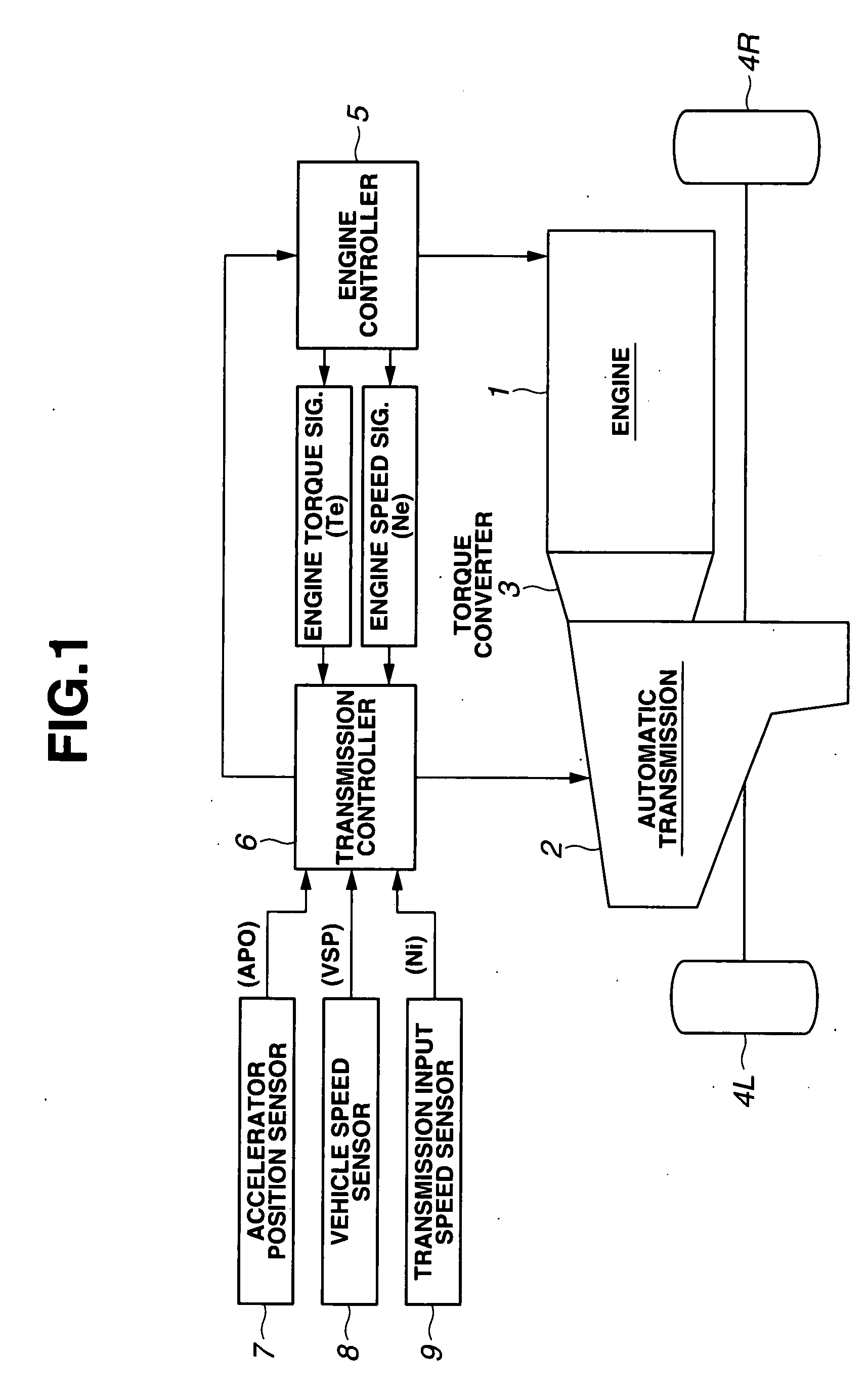
[0036]Referring now to the drawings, particularly to FIG. 1, the engine output control apparatus of the embodiment is exemplified in a power train of an automotive vehicle employing both an engine 1 and an automatic transaxle in which an automatic transmission 2 and a differential gear are combined with each other as a unit. As seen in FIG. 1, a coupling / uncoupling device 3 is disposed between engine 1 and automatic transmission 2 for performing coupling and uncoupling actions between the engine and the transmission. In the shown embodiment, a torque converter is used as coupling / uncoupling device 3, whereas a continuously variable transmission, abbreviated to “CVT”, such as a belt-drive CVT or a toroidal CVT is used as automatic transmission 2. Instead of using such a torque converter, an electromagnetic clutch may be used as coupling / uncoupling device 3. Instead of using such a CVT, a stepped automatic transmission, whose number of speeds is limited or finite, may be used. Front-l...


PUM


Abstract

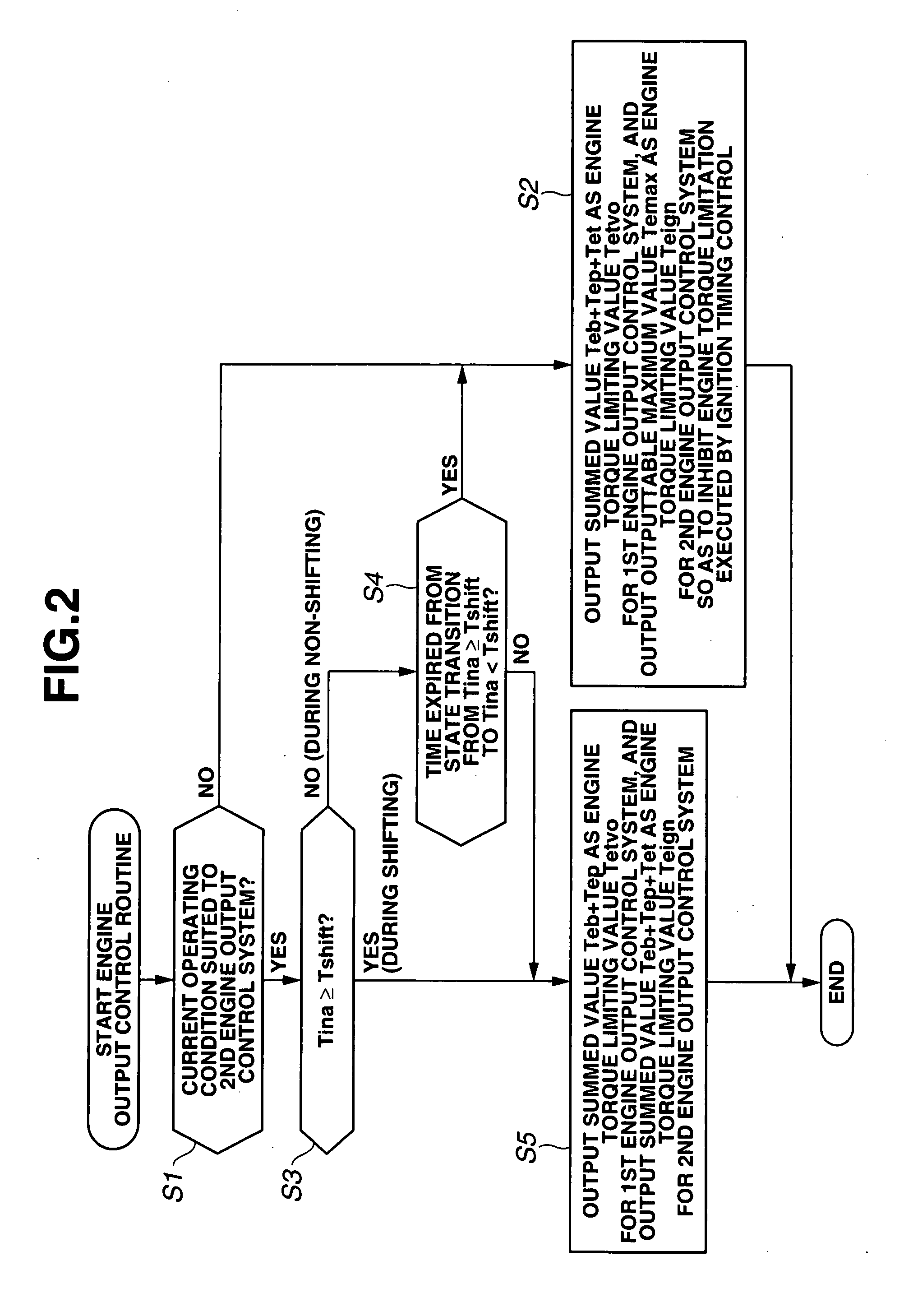
In an engine output control apparatus of a power train employing an engine and an automatic transmission, capable of executing engine output control for excessive torque input prevention engine torque limiting action and for a shift speed control of the transmission, at least two different kinds of engine output control systems having control characteristics differing from each other, are provided. A controller selectively uses these engine output control systems depending on a power-train operating condition, such that a first one of the engine output control systems having a superior transient response is used for the engine output control for shift response control during shifting, and that a second one of the engine output control systems having a superior steady-state stability is used for the engine output control for excessive torque input prevention engine torque limiting action during non-shifting.

Description

TECHNICAL FIELD[0001]The present invention relates to an engine output control apparatus of a power train employing an engine and an automatic transmission, and specifically to the improvement of an engine output control technology capable of executing engine torque control for preventing the input of an excessive magnitude of torque exceeding a critical torque value (an upper limit of transmittable torque) transmitted through the power train and for controlling a shift speed (a shift response) of the automatic transmission.BACKGROUND ART[0002]An engine output control apparatus, which executes engine output control for preventing an excessive torque input exceeding an upper limit of transmittable torque transmitted through a power train, has been disclosed in Japanese Patent Provisional Publication No. 2004-092522 (hereinafter is referred to as “JP2004-092522”). The engine output control device disclosed in JP2004-092522 is exemplified in a power train constructed by an engine and a...

Claims


Application Information

Patent Timeline
Patent Type & Authority Applications(United States)
IPC IPC(8): G06F19/00F02P5/00B60W10/10
CPCB60K2741/145B60W50/06F02D2200/602F02P5/1504F16H35/10Y10T477/68F16H61/66272F16H63/502F16H2306/42Y02T10/46F16H61/66259B60W10/04B60W10/101B60W30/1819Y02T10/40
Inventor KADONO, RYOUJIIRIYAMA, MASAHIROFUKE, TETSUYAOOTAKI, RYOUICHIKIMURA, YUSUKEOCHIAI, TATSUO
Owner NISSAN MOTOR CO LTD
Learn More