Eureka AIR delivers breakthrough ideas for toughest innovation challenges, trusted by R&D personnel around the world.

Method for monitoring a hearing device and hearing device with self-monitoring function

a hearing device and self-monitoring technology, applied in the direction of hearing aid testing/monitoring, deaf-aid sets, electric devices, etc., can solve the problems of loudspeaker performance, wax filter performance cannot be fully protected from wax blockage, loudspeaker performance may be significantly deteriorated, etc., to optimize the acoustical performance of the hearing device, simple and efficient

Active Publication Date: 2007-12-13
SONOVA AG
View PDF6 Cites 53 Cited by
  • Summary
  • Abstract
  • Description
  • Claims
  • Application Information

AI Technical Summary

Benefits of technology

[0011]The invention is generally beneficial in that, by measuring and analyzing the electrical impedance of the output transducer, the status of the output transducer and / or of an acoustical system cooperating with the output transducer, such as a tubing of a BTE hearing device, may be evaluated in a simple and efficient manner. According to one aspect, thereby it is enabled to automatically and immediately recognize when the output transducer or an acoustical system cooperating with the output transducer is blocked by ear wax or when the output transducer is damaged. According to another aspect, thereby the length and / or diameter of the tubing of a BTE hearing device can be automatically determined in a simple manner, and the thus determined length and / or diameter of the tubing can be used to optimize the operation parameters of the hearing device according the determined length and / or diameter of the tubing in order to optimize the acoustical performance of the hearing device.

Problems solved by technology

A frequent problem of such ear-worn hearing devices is that the performance of the loudspeaker may be significantly deteriorated due to blocking with ear wax (cerumen) from the ear canal.
However, none of these wax filters is capable of providing for a full protection from wax blocking.
If the loudspeaker performance is deteriorated by wax blocking, the user may not immediately notice this.
This may be particularly true for systems used by children, since they usually have much more difficulty in noticing and communicating problems regarding the hearing device.

Method used


Image

  • Method for monitoring a hearing device and hearing device with self-monitoring function
  • Method for monitoring a hearing device and hearing device with self-monitoring function
  • Method for monitoring a hearing device and hearing device with self-monitoring function

Examples


Embodiment Construction

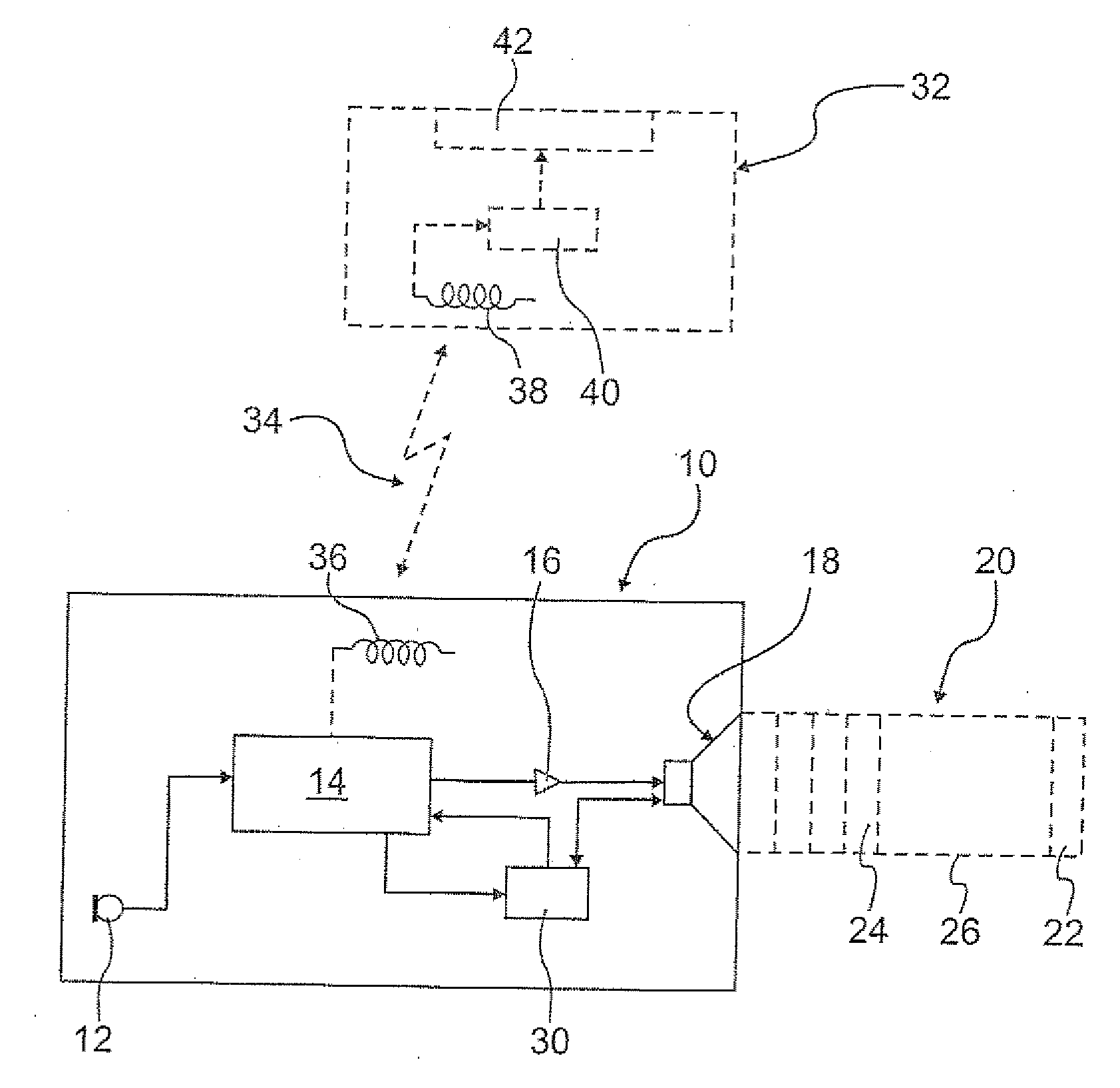
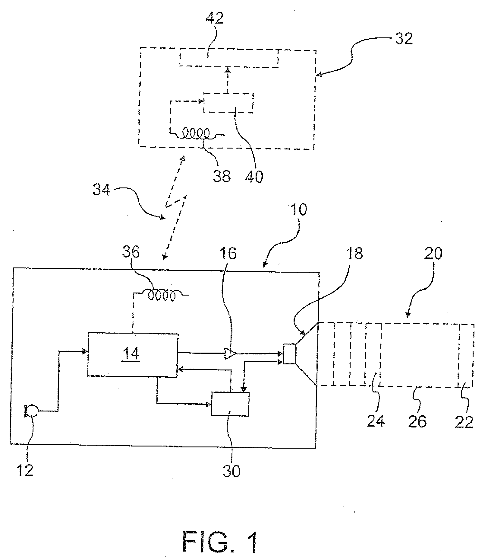
[0019]FIG. 1 is a block diagram of a first example of a hearing device for which the invention can be used, wherein the hearing device is a hearing aid 10 which comprises a microphone arrangement 12 (which may consist of two spaced-apart microphones for enabling acoustic beam forming capability), a central processing unit 14 for processing the audio signals produced by the microphone arrangement 12, a power amplifier 16 for amplifying the processed audio signals from the central processing unit 14, and a loudspeaker 18 for stimulating the user's hearing with the processed amplified audio signals from the microphone arrangement 12. The hearing aid 10 could be of the ITE or CIC type, in which cases the loudspeaker 18 would be located in the ear canal of the user.

[0020]The loudspeaker 18 may cooperate with an acoustical system 20 located downstream of the loudspeaker 18, which may comprise, for example, a wax filter 22, acoustical filters 24 and some kind of tubing 26. Such tubing 26 w...


PUM


Abstract

There is provided a method for monitoring a hearing device comprising an electroacoustic output transducer worn at a user's ear or in a user's ear canal, the method comprising: measuring the electrical impedance of the output transducer; analyzing the measured electrical impedance of the output transducer in order to evaluate the status of the output transducer and / or of an acoustical system cooperating with the output transducer; and outputting a status signal representative of the status of the output transducer and / or of the acoustical system cooperating with the output transducer.

Description

BACKGROUND OF THE INVENTION[0001]1. Field of the Invention[0002]The invention relates to a method for monitoring a hearing device comprising an electro-acoustic output transducer worn at a user's ear or in a user's ear canal. The invention also relates to such a hearing device having self-monitoring function. According to another aspect, the invention relates to a method for adjusting a behind-the-ear hearing device and also to such an adjustable behind-the-ear hearing device.[0003]2. Description of Related Art[0004]Ear-worn hearing devices, such as hearing aids (which have an integrated microphone system) or wireless systems (which comprise a remote audio signal source, such as a remote microphone, and an ear-piece receiver) usually comprise an electro-acoustic output transducer (loudspeaker) which is located in or at least close to the ear canal. This applies particularly to in-the-ear (ITE) or completely in-the-canal (CIC) systems. However, also behind-the-ear (BTE) systems have ...

Claims


Application Information

Patent Timeline
IPC IPC(8): H04R25/00
CPCH04R25/30
Inventor HARSCH, SAMUELDIJKSTRA, EVERT
Owner SONOVA AG
Why Eureka
Eureka Blog
Learn More