
Developer supply device and image forming apparatus comprising same

a technology of developing devices and developing apparatuses, applied in the field of image forming apparatuses using electrophotography, can solve problems such as abnormal images, carrier deterioration, and image quality such as image density and the like may be unstable, and achieve the effect of stable toner concentration and high degree of freedom

Inactive Publication Date: 2007-12-06
RICOH KK
View PDF37 Cites 35 Cited by
  • Summary
  • Abstract
  • Description
  • Claims
  • Application Information

AI Technical Summary

Benefits of technology

[0016]In order to solve the above-described problems, it is an object of the invention to provide a developer supply device, as well as a developer container and a developer used in this developer supply device, such that the developer is discharged stably from the developer container with a stable toner concentration in the developer, without damaging the developer, and in a relatively simple and small-size device having a relatively high degree of freedom as regards layout.

Problems solved by technology

During an ordinary developing process, thus, the carrier in the two-component developer held in the developing device remains inside the developing device without becoming consumed, and, as a result, the carrier deteriorates over time.
Image quality such as image density and the like may be become unstable when the proportions of toner and carrier (toner concentration) cannot be kept constant in the developer that is being transported towards the developing device.
Also, toner aggregates may also form during the rotation of the bottle-shaped developer container, which may give rise to abnormal images such as white spots and the like.
That is, if the carrier gap in the developer container is insufficient, it is highly probable that the developer cannot be supplied (discharged) stably from the developer container, but providing the above-described gap in a sufficient manner results in the developer container having a larger size.

Method used


Image

  • Developer supply device and image forming apparatus comprising same
  • Developer supply device and image forming apparatus comprising same
  • Developer supply device and image forming apparatus comprising same

Examples


first embodiment

[0030]The first embodiment is explained with reference to FIGS. 1 to 4.

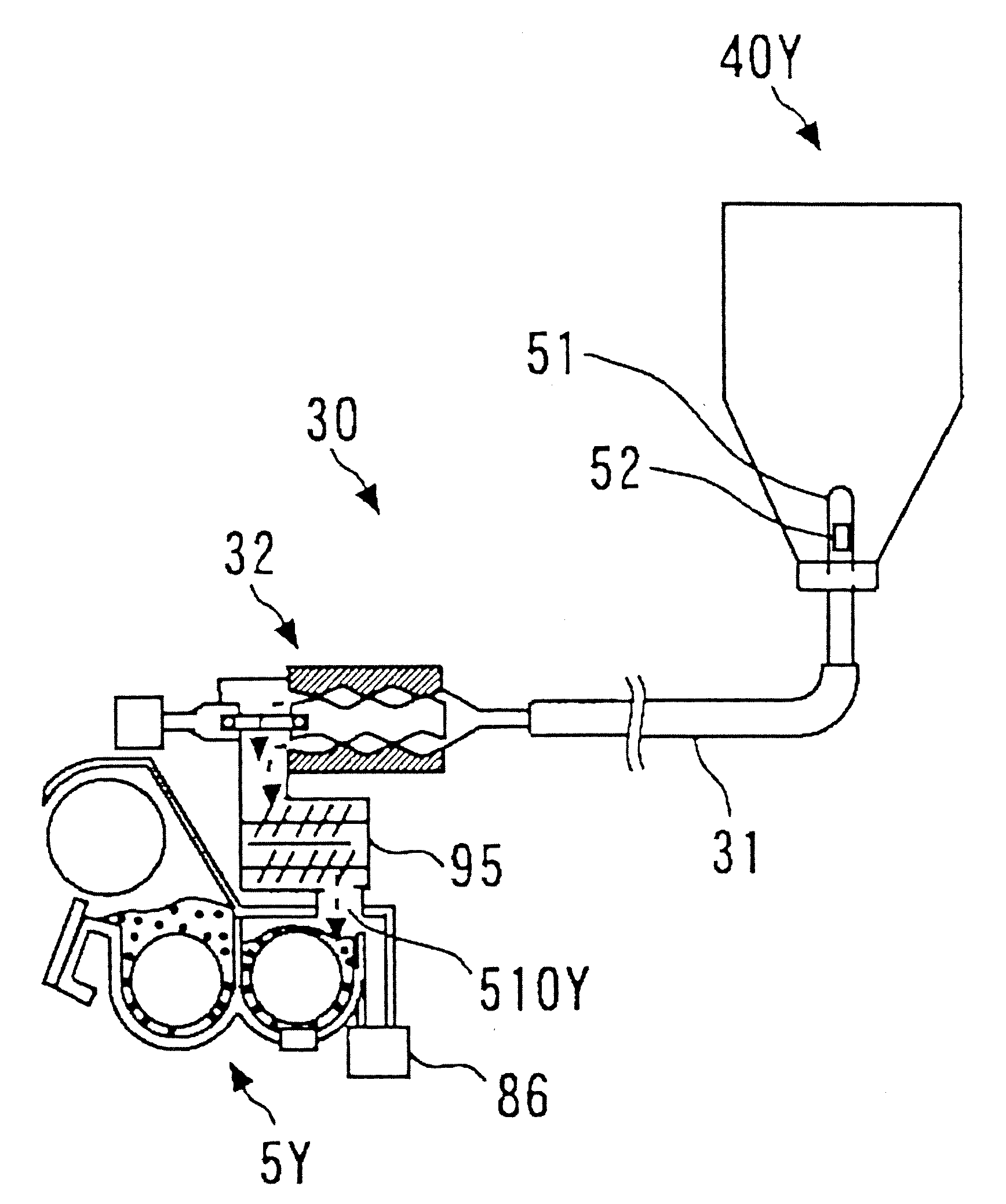
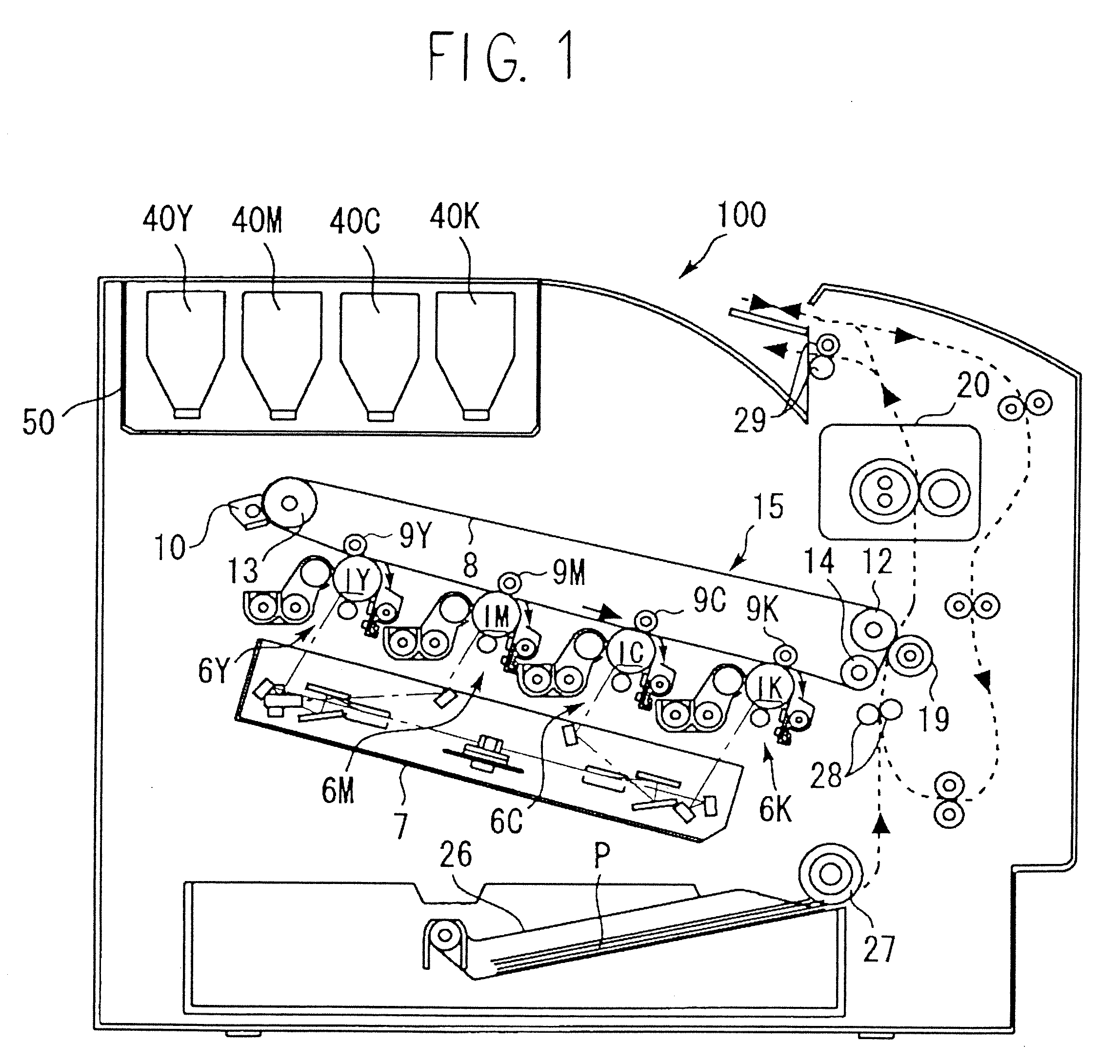
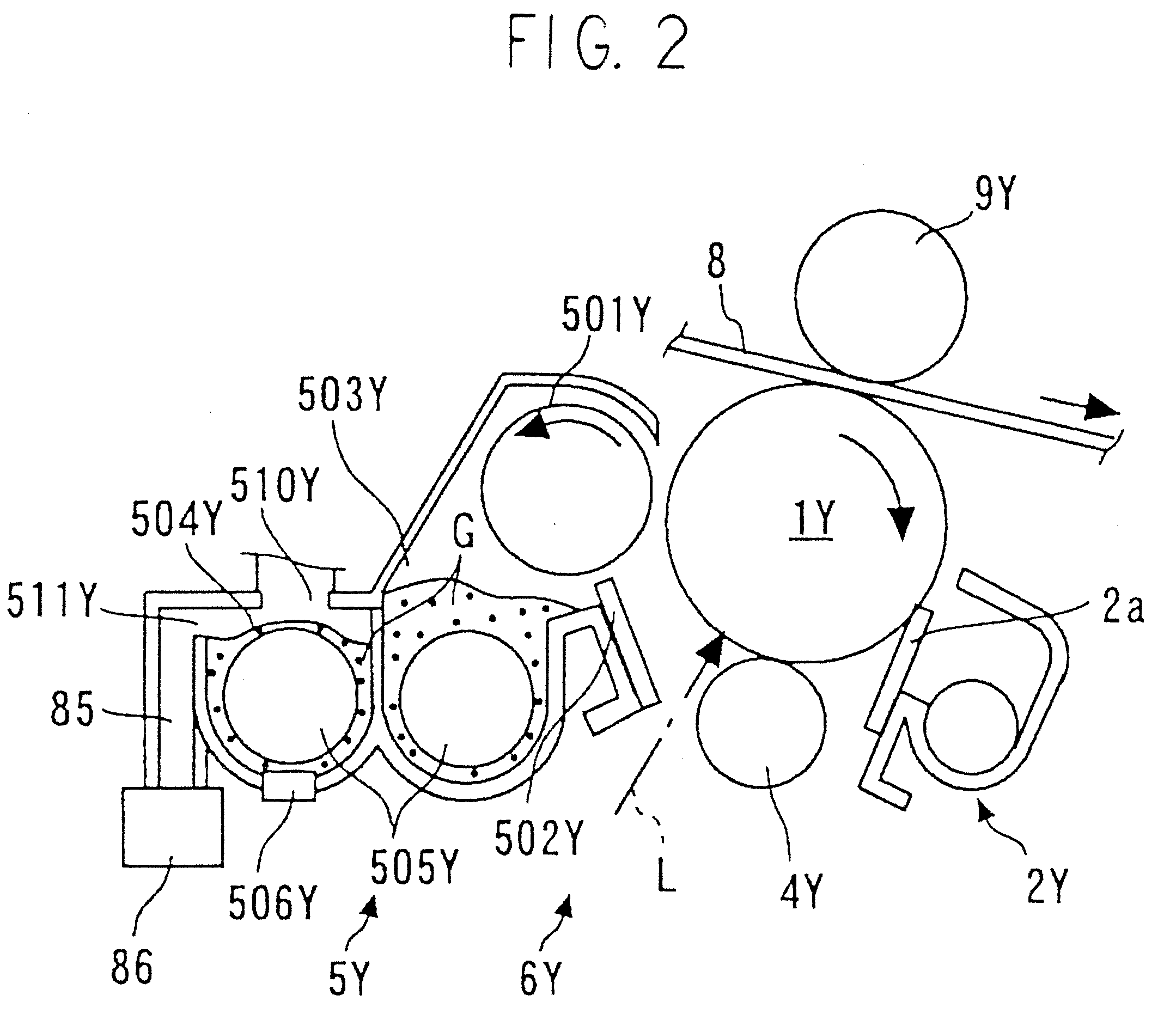
[0031]FIG. 1 is an overall schematic diagram illustrating a printer as the image forming apparatus; FIG. 2 is an enlarged diagram illustrating image forming units thereof; FIG. 3 is a schematic diagram illustrating a developer supply channel thereof; and FIG. 4 is a cross-sectional diagram illustrating a developer supply device.

[0032]As illustrated in FIG. 1, four developer containers 40Y, 40M, 40C and 40K corresponding to various colors (yellow, magenta, cyan, and black) are removably (exchangeably) arranged on a developer container holding unit 50 provided on the upper portion of an image forming apparatus body 100. Below the developer container holding unit 50 there is arranged an intermediate transfer unit 15. Image forming units 6Y, 6M, 6C and 6K corresponding to various colors (yellow, magenta, cyan, and black) are provided so as to oppose an intermediate transfer belt 8 of the intermediate transfer unit 15...

second embodiment

[0133]A second embodiment of the present invention is explained in detail next with reference to FIG. 5.

[0134]FIG. 5 is a diagram illustrating the overall constitution of an image forming apparatus according to this embodiment of the invention. The image forming apparatus of this embodiment differs from that of the first embodiment in that the image forming units 6Y, 6M, 6C and 6K are arrayed above the intermediate transfer unit 15 while in the first embodiment the image forming units 6Y, 6M, 6C and 6K are arrayed below the intermediate transfer unit 15.

[0135]As illustrated in FIG. 5, the image forming apparatus 100 according to the present embodiment has the image forming units 6Y, 6M, 6C and 6K arrayed above the intermediate transfer unit 15. As in the first embodiment, each of the image forming units 6Y, 6M, 6C and 6K comprises, for instance, a photoconductive drum, a charger, a developing device (developing unit), a cleaner and a discharger.

[0136]In the present embodiment, in FI...

example 1

[0164]90 parts of the toner a and 10 parts of the carrier e were stirred and mixed in a tabular mixer, to prepare a developer (premix toner). This developer in an amount of 975 g was filled into a developer container 40 (for black toner) having a capacity of 2650 cm3 in which the air layer took up 35 to 40 vol %. The developer was set in the developer supply device of the image forming apparatus in the second embodiment was set and dischargeability (replenishability) was checked. FIG. 6 illustrates the results obtained. The developer filling the developer container 40 was discharged stably from the developer container.

[0165]Next, 7 parts of the toner a and 93 parts of the carrier e were stirred and mixed in a tabular mixer, to yield a developer (initial agent). This developer was filled into a developer container of the second embodiment, and then a running test was carried out in which 100,000 sheets having a monochrome image with an image surface area of 20% were continuously outp...


PUM


Abstract

The invention provides a developer supply device, a developer container, a developer and an image forming apparatus such that the developer is discharged stably from the developer container with a stable toner concentration in the developer, without damaging the developer, and in a relatively simple and small-size device having a relatively high degree of freedom as regards layout. The developer supply device comprises a partially or wholly deformable developer container and a pump for suctioning the developer held in the developer container, together with a gas, and for discharging the developer towards a developing unit. The toner comprises an additive formed so as to have a volume average particle size of 50 to 500 nm. The carrier is formed so as to have a weight average particle size of 20 to 60 μm. The developer is formed so that the carrier concentration thereof is 1 to 30 wt %.

Description

BACKGROUND OF THE INVENTION[0001]1. Field of the Invention[0002]The present invention relates to an image forming apparatus using electrophotography, such as, for instance, a copying machine, a printer, a fax device, or a multifunction device comprising the foregoing, and more particularly to a developer supply device for supplying a two-component developer comprising a toner and a carrier to a developing unit, and relates to a developer container and a developer used in this developer supply device.[0003]2. Description of the Related Art[0004]Conventional image forming apparatuses using electrophotography, such as copying machines, printers and the like, use known technologies (for instance, as disclosed in Japanese Unexamined Patent Application Laid-open No. 2001-194860) in which developer is replaced by suitably replenishing a fresh two-component developer into a developing unit (developing device) that holds a two-component developer comprising a toner and a carrier (including d...

Claims


Application Information

Patent Timeline
IPC IPC(8): G03G15/08
CPCG03G2215/0607G03G2215/0682G03G15/0855G03G15/0879G03G15/0865G03G15/0874
Inventor MATSUMOTO, KEIKOUNO, MUGIJIROUOKAJI, HIROYUKI
Owner RICOH KK
Learn More