[0006]In view of the above, the invention provides a zoom lens small in size but high in performance that allows power variation on a relatively telephoto side.
[0008]In the zoom lens of this configuration, the power of the zoom lens varies by moving the second group along the optical axis with the first and third groups fixed. The fourth group is moved along the optical axis to perform correction of the position of the
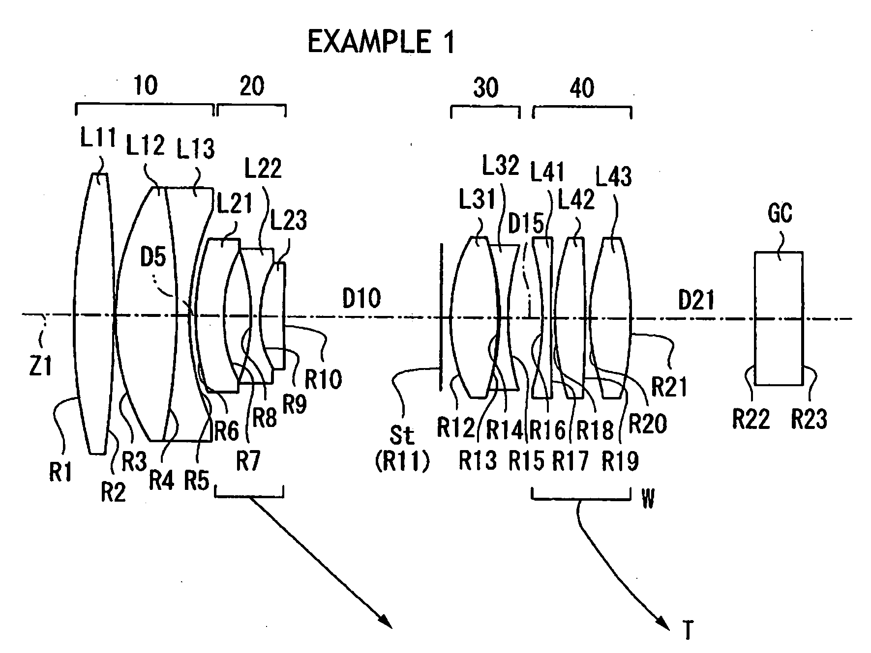
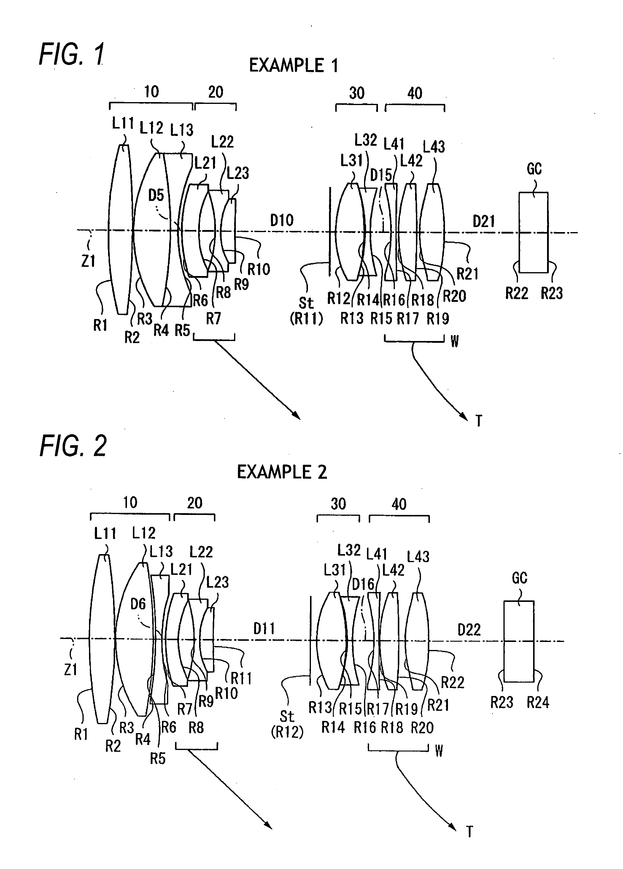
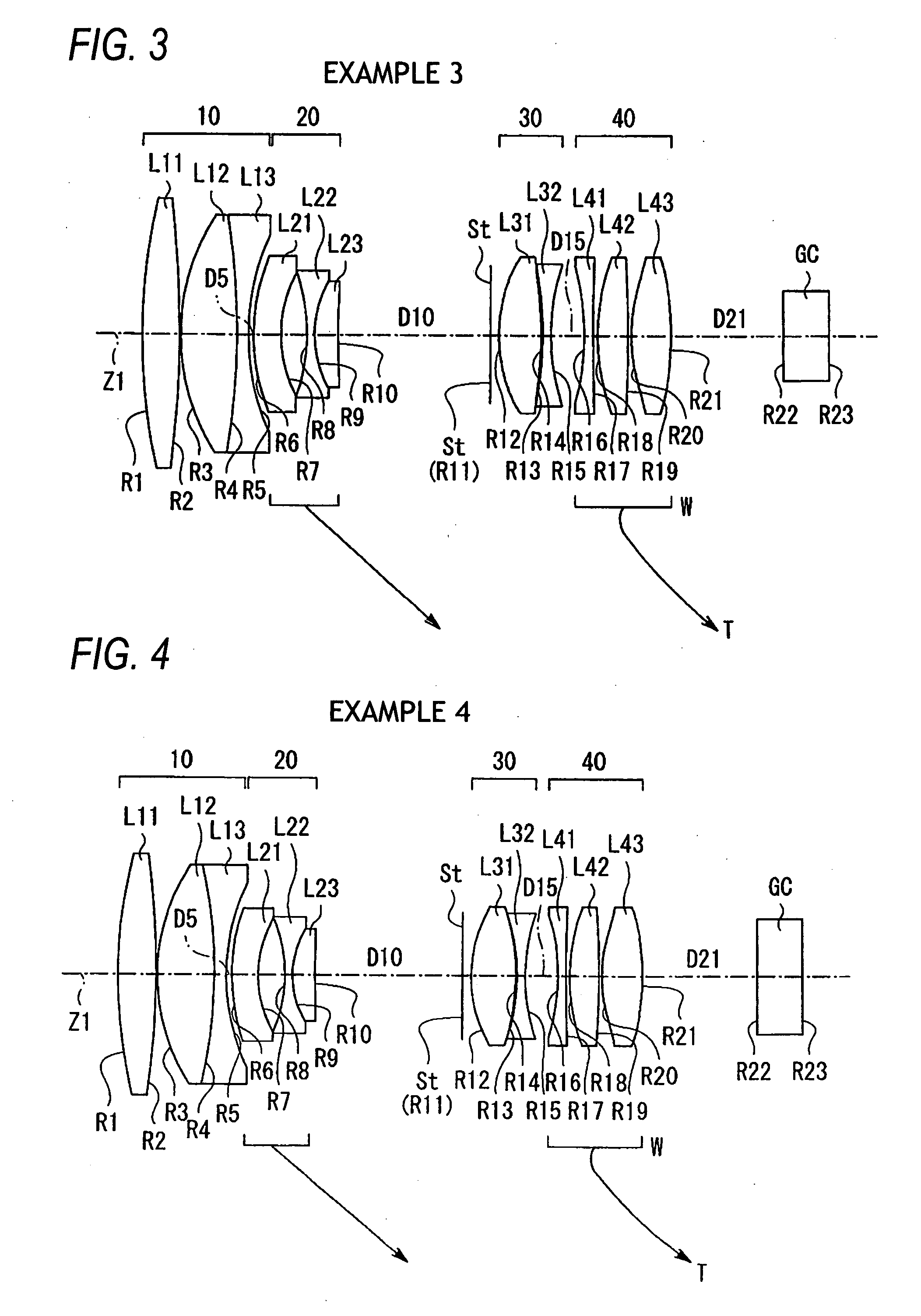
image plane and focusing, which is required due to the variation of the power. Particularly, since the first group is configured so that positive, positive and negative lenses are arranged in order from the object side, power arrangement in the first group is optimized, which is advantageous in reducing the size.
[0010]A combined refractive power of the second and third lenses of the first group may be negative. This configuration is advantageous in reducing the length of the lens. Also, the second and third lenses of the first group may form a cemented lens. This configuration can avoid the performance deterioration caused by assembling error. Also, in order to obtain a good optical performance in the visible region, at least one lens of the first group satisfies the following
conditional expression (1). Furthermore, in order to achieve a good optical performance over from the visible region to near-
infrared region, the following
conditional expression (2) may be satisfied. It is noted that νd denotes an
Abbe number at d-line having 587.6 nm in
wavelength.νd>50 (1)νd>75 (2)
[0011]The second group may include, in order from the object side, a first lens of the second group having a negative refractive power, a second lens of the second group having a biconcave shape and a third lens of the second group having a positive refractive power. By providing the cemented lens, performance deterioration due to assembling error can be avoided. Also, the second group may further include a lens having a positive or negative refractive power on the object side of the first lens of the second group or on the image side of the third lens of the second group. This configuration is advantageous in reducing the aberration variation due to power variation. Furthermore, the third lens of the second group satisfies the following
conditional expression (3). This configuration suppresses the movement amount of the second group, which is advantageous in reducing the size. It is noted that N23 denotes a
refractive index of the third lens of the second group at d-line having 587.6 nm in
wavelength.N23>1.75 (3)
[0012]The third group may include at least one lens having a positive refractive power and at least one lens having a negative refractive power. This configuration is advantageous in correcting the longitudinal
chromatic aberration caused in the third group, thus making it possible to increase the
aperture ratio. In this case, the third group may include, in order from the object side, a first
single lens of the third group having a positive refractive power and a second
single lens of the third group having a negative refractive power with a
concave surface directed to the object side. This configuration is advantageous in
size reduction and cost reduction. Alternatively, the third group may include a cemented lens formed of a first lens of the third group having a positive refractive power and a second lens of the third group having a negative refractive power with the first and second lenses of the third group arranged in order from the object side. This configuration is advantageous in the capability to avoid the performance deterioration due to assembling error. Also, the least one lens of the third group having the positive refractive power may have at least one aspheric surface. This configuration can increase the
aperture ratio while maintaining the
size reduction.
[0013]The fourth group may have a positive refractive power. Also, the fourth group may include, in order from the object side, a first lens of the fourth group having a negative refractive power with a
concave surface directed to the object side, a second lens of the fourth group having a positive refractive power and a third lens of the fourth group having a positive refractive power. At least one surface of the lenses of the fourth group having the positive refractive power may be aspheric. This configuration is advantageous in correcting aberrations and can increase the
aperture ratio. In this case, at least one surface of the third lens of the fourth group may be aspheric. Also, at least one lens of the fourth group satisfies the following conditional expression (4). This configuration can prevent the longitudinal
chromatic aberration from increasing over the entire power variation range of from the wide-angle end to the telephoto end.νd>75 (4)
